

Programmable Controllers: Theory and Implementation
Programmable Controllers: Theory and Implementation
Programmable Controllers: Theory and Implementation
- No tags were found...

Create successful ePaper yourself
Turn your PDF publications into a flip-book with our unique Google optimized e-Paper software.
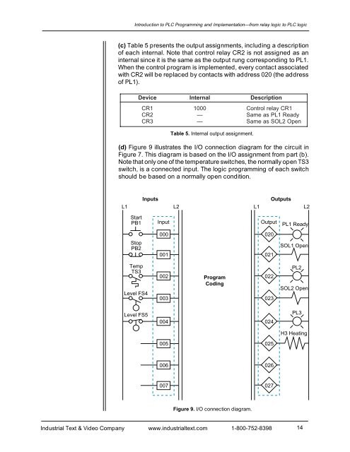
Introduction to PLC Programming <strong>and</strong> <strong>Implementation</strong>—from relay logic to PLC logic(c) Table 5 presents the output assignments, including a descriptionof each internal. Note that control relay CR2 is not assigned as aninternal since it is the same as the output rung corresponding to PL1.When the control program is implemented, every contact associatedwith CR2 will be replaced by contacts with address 020 (the addressof PL1).DeviceInternalTable 5. Internal output assignment.DescriptionCR11000Control relay CR1C R2— Same as PL1 ReadyC R3— Same as SOL2 Open(d) Figure 9 illustrates the I/O connection diagram for the circuit inFigure 7. This diagram is based on the I/O assignment from part (b).Note that only one of the temperature switches, the normally open TS3switch, is a connected input. The logic programming of each switchshould be based on a normally open condition.InputsOutputsL1 L2L1 L2StartPB1StopPB2TempTS3Level FS4Input000001 021002ProgramCodingOutput020022003 023PL1 ReadySOL1 OpenPL2SOL2 OpenLevel FS5004024PL3H3 Heating005025006026007027Figure 9. I/O connection diagram.Industrial Text & Video Company www.industrialtext.com 1-800-752-839814


