

Programmable Controllers: Theory and Implementation
Programmable Controllers: Theory and Implementation
Programmable Controllers: Theory and Implementation
- No tags were found...

You also want an ePaper? Increase the reach of your titles
YUMPU automatically turns print PDFs into web optimized ePapers that Google loves.
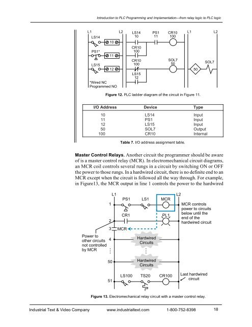
Introduction to PLC Programming <strong>and</strong> <strong>Implementation</strong>—from relay logic to PLC logicL1 L2 LS14 PS1 CR10 L1 L2LS1410 11 10010PS1*LS151112*Wired NCProgrammed NOCR10100CR10100LS1512SOL750Figure 12. PLC ladder diagram of the circuit in Figure 11.50SOL7I/O AddressDevice10LS1411PS112LS1550SOL7100CR10TypeInputInputInputOutputInternalTable 7. I/O address assignment table.Master Control Relays. Another circuit the programmer should be awareof is a master control relay (MCR). In electromechanical circuit diagrams,an MCR coil controls several rungs in a circuit by switching ON or OFFthe power to those rungs. In a hardwired circuit, there is no definite end to anMCR except when the circuit is followed all the way through. For example,in Figure13, the MCR output in line 1 controls the power to the hardwired123L1PS1CR1MCRLS1MCRPL1L2MCR controlspower to circuitsbelow until theend of thehardwired circuitPower toother circuitsnot controlledby MCR4HardwiredCircuits50 HardwiredCircuits51LS100TS20CR100Last hardwiredcircuitFigure 13. Electromechanical relay circuit with a master control relay.Industrial Text & Video Company www.industrialtext.com 1-800-752-839818


