

Programmable Controllers: Theory and Implementation
Programmable Controllers: Theory and Implementation
Programmable Controllers: Theory and Implementation
- No tags were found...

Create successful ePaper yourself
Turn your PDF publications into a flip-book with our unique Google optimized e-Paper software.
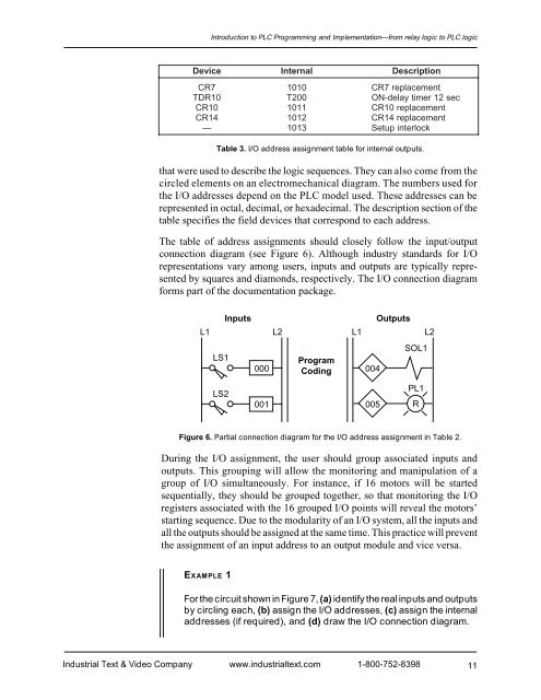
Introduction to PLC Programming <strong>and</strong> <strong>Implementation</strong>—from relay logic to PLC logicDeviceInternalDescriptionCR71010CR7 replacementTDR10T200ON-delay timer 12 secCR101011CR10 replacementCR141012CR14 replacement— 1013Setup interlockTable 3. I/O address assignment table for internal outputs.that were used to describe the logic sequences. They can also come from thecircled elements on an electromechanical diagram. The numbers used forthe I/O addresses depend on the PLC model used. These addresses can berepresented in octal, decimal, or hexadecimal. The description section of thetable specifies the field devices that correspond to each address.The table of address assignments should closely follow the input/outputconnection diagram (see Figure 6). Although industry st<strong>and</strong>ards for I/Orepresentations vary among users, inputs <strong>and</strong> outputs are typically representedby squares <strong>and</strong> diamonds, respectively. The I/O connection diagramforms part of the documentation package.L1 L2L1 L2LS1InputsProgram000 Coding 004OutputsSOL1LS2001 005PL1RFigure 6. Partial connection diagram for the I/O address assignment in Table 2.During the I/O assignment, the user should group associated inputs <strong>and</strong>outputs. This grouping will allow the monitoring <strong>and</strong> manipulation of agroup of I/O simultaneously. For instance, if 16 motors will be startedsequentially, they should be grouped together, so that monitoring the I/Oregisters associated with the 16 grouped I/O points will reveal the motors’starting sequence. Due to the modularity of an I/O system, all the inputs <strong>and</strong>all the outputs should be assigned at the same time. This practice will preventthe assignment of an input address to an output module <strong>and</strong> vice versa.EXAMPLE 1For the circuit shown in Figure 7, (a) identify the real inputs <strong>and</strong> outputsby circling each, (b) assign the I/O addresses, (c) assign the internaladdresses (if required), <strong>and</strong> (d) draw the I/O connection diagram.Industrial Text & Video Company www.industrialtext.com 1-800-752-839811


