

Programmable Controllers: Theory and Implementation
Programmable Controllers: Theory and Implementation
Programmable Controllers: Theory and Implementation
- No tags were found...

Create successful ePaper yourself
Turn your PDF publications into a flip-book with our unique Google optimized e-Paper software.
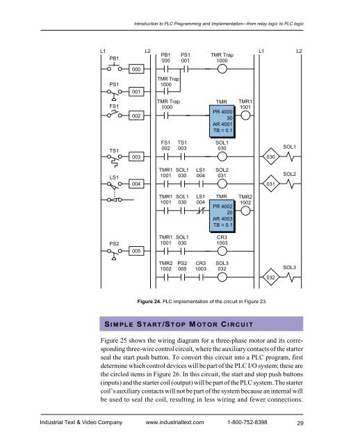
Introduction to PLC Programming <strong>and</strong> <strong>Implementation</strong>—from relay logic to PLC logicL1 L2L1 L2PB1 PS1 TMR TrapPB1000 0011000PS1FS1000001002TMR Trap1000TMR Trap1000TMRPR 400030AR 4001TB = 0.1TMR11001TS1003FS1002TS1003SOL1030030SOL1LS1004TMR11001SOL1030LS1004SOL2031031SOL2TMR11001SOL1030LS1004TMRPR 400220AR 4003TB = 0.1TMR21002PS2005TMR11001SOL1030CR31003TMR21002PS2005CR31003SOL3032SOL3032Figure 24. PLC implementation of the circuit in Figure 23.SIMPLE START/STOP MOTOR CIRCUITFigure 25 shows the wiring diagram for a three-phase motor <strong>and</strong> its correspondingthree-wire control circuit, where the auxiliary contacts of the starterseal the start push button. To convert this circuit into a PLC program, firstdetermine which control devices will be part of the PLC I/O system; these arethe circled items in Figure 26. In this circuit, the start <strong>and</strong> stop push buttons(inputs) <strong>and</strong> the starter coil (output) will be part of the PLC system. The startercoil’s auxiliary contacts will not be part of the system because an internal willbe used to seal the coil, resulting in less wiring <strong>and</strong> fewer connections.Industrial Text & Video Company www.industrialtext.com 1-800-752-839829


