

Programmable Controllers: Theory and Implementation
Programmable Controllers: Theory and Implementation
Programmable Controllers: Theory and Implementation
- No tags were found...

You also want an ePaper? Increase the reach of your titles
YUMPU automatically turns print PDFs into web optimized ePapers that Google loves.
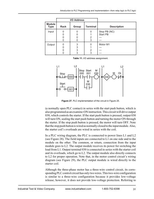
Introduction to PLC Programming <strong>and</strong> <strong>Implementation</strong>—from relay logic to PLC logicI/O AddressModuleTypeRackGroupTerminalDescriptionInput0 0 0 Stop PB (NC)0 0 1 Start PB0 0 2 —0 0 3 —Output0 3 0 Motor M10 3 1 —0 3 2 —0 3 3 —Table 11. I/O address assignment.L1001L2Stop Start MStop 000 001 030M OL000030StartM030L1L2Figure 27. PLC implementation of the circuit in Figure 25.(a normally open PLC contact) in series with the start push button, which isalso programmed as an examine-ON instruction. This circuit will drive output030, which controls the starter. If the start push button is pressed, output 030will turn ON, sealing the start push button <strong>and</strong> turning the motor ON throughthe starter. If the stop push button is pressed, the motor will turn OFF. Notethat the stop push button is wired as normally closed to the input module. Also,the starter coil’s overloads are wired in series with the coil.In a PLC wiring diagram, the PLC is connected to power lines L1 <strong>and</strong> L2(see Figure 28). The field inputs are connected to L1 on one side <strong>and</strong> to themodule on the other. The common, or return, connection from the inputmodule goes to L2. The output module receives its power for switching theload from L1. Output terminal 030 is connected in series with the starter coil<strong>and</strong> its overloads, which go to L2. The output module also directly connectsto L2 for proper operation. Note that, in the motor control circuit’s wiringdiagram (see Figure 29), the PLC output module is wired directly to thestarter coil.Although the three-phase motor has a three-wire control circuit, its correspondingPLC control circuit has only two wires. This two-wire configurationis similar to a three-wire configuration because it provides low-voltagerelease; however, it does not provide low-voltage protection. Referring toIndustrial Text & Video Company www.industrialtext.com 1-800-752-839831


