Programmable Controllers: Theory and Implementation
Programmable Controllers: Theory and Implementation
Programmable Controllers: Theory and Implementation
- No tags were found...
Create successful ePaper yourself
Turn your PDF publications into a flip-book with our unique Google optimized e-Paper software.
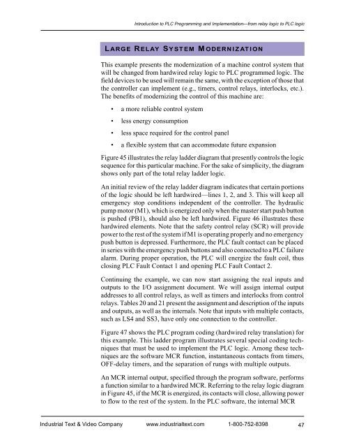
Introduction to PLC Programming <strong>and</strong> <strong>Implementation</strong>—from relay logic to PLC logicLARGE RELAY SYSTEM MODERNIZATIONThis example presents the modernization of a machine control system thatwill be changed from hardwired relay logic to PLC programmed logic. Thefield devices to be used will remain the same, with the exception of those thatthe controller can implement (e.g., timers, control relays, interlocks, etc.).The benefits of modernizing the control of this machine are:• a more reliable control system• less energy consumption• less space required for the control panel• a flexible system that can accommodate future expansionFigure 45 illustrates the relay ladder diagram that presently controls the logicsequence for this particular machine. For the sake of simplicity, the diagramshows only part of the total relay ladder logic.An initial review of the relay ladder diagram indicates that certain portionsof the logic should be left hardwired—lines 1, 2, <strong>and</strong> 3. This will keep allemergency stop conditions independent of the controller. The hydraulicpump motor (M1), which is energized only when the master start push buttonis pushed (PB1), should also be left hardwired. Figure 46 illustrates thesehardwired elements. Note that the safety control relay (SCR) will providepower to the rest of the system if M1 is operating properly <strong>and</strong> no emergencypush button is depressed. Furthermore, the PLC fault contact can be placedin series with the emergency push buttons <strong>and</strong> also connected to a PLC failurealarm. During proper operation, the PLC will energize the fault coil, thusclosing PLC Fault Contact 1 <strong>and</strong> opening PLC Fault Contact 2.Continuing the example, we can now start assigning the real inputs <strong>and</strong>outputs to the I/O assignment document. We will assign internal outputaddresses to all control relays, as well as timers <strong>and</strong> interlocks from controlrelays. Tables 20 <strong>and</strong> 21 present the assignment <strong>and</strong> description of the inputs<strong>and</strong> outputs, as well as the internals. Note that inputs with multiple contacts,such as LS4 <strong>and</strong> SS3, have only one connection to the controller.Figure 47 shows the PLC program coding (hardwired relay translation) forthis example. This ladder program illustrates several special coding techniquesthat must be used to implement the PLC logic. Among these techniquesare the software MCR function, instantaneous contacts from timers,OFF-delay timers, <strong>and</strong> the separation of rungs with multiple outputs.An MCR internal output, specified through the program software, performsa function similar to a hardwired MCR. Referring to the relay logic diagramin Figure 45, if the MCR is energized, its contacts will close, allowing powerto flow to the rest of the system. In the PLC software, the internal MCRIndustrial Text & Video Company www.industrialtext.com 1-800-752-839847


