

PIC16F84A 18-pin Enhanced Flash/EEPROM 8-Bit MCU Data Sheet
PIC16F84A 18-pin Enhanced Flash/EEPROM 8-Bit MCU Data Sheet
PIC16F84A 18-pin Enhanced Flash/EEPROM 8-Bit MCU Data Sheet

Create successful ePaper yourself
Turn your PDF publications into a flip-book with our unique Google optimized e-Paper software.
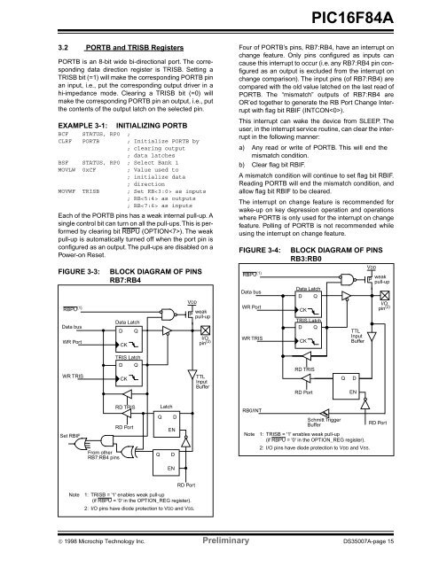
<strong>PIC16F84A</strong>3.2 PORTB and TRISB RegistersPORTB is an 8-bit wide bi-directional port. The correspondingdata direction register is TRISB. Setting aTRISB bit (=1) will make the corresponding PORTB <strong>pin</strong>an input, i.e., put the corresponding output driver in ahi-impedance mode. Clearing a TRISB bit (=0) willmake the corresponding PORTB <strong>pin</strong> an output, i.e., putthe contents of the output latch on the selected <strong>pin</strong>.EXAMPLE 3-1: INITIALIZING PORTBBCF STATUS, RP0 ;CLRF PORTB ; Initialize PORTB by; clearing output; data latchesBSF STATUS, RP0 ; Select Bank 1MOVLW 0xCF; Value used to; initialize data; directionMOVWF TRISB ; Set RB as inputs; RB as outputs; RB as inputsEach of the PORTB <strong>pin</strong>s has a weak internal pull-up. Asingle control bit can turn on all the pull-ups. This is performedby clearing bit RBPU (OPTION). The weakpull-up is automatically turned off when the port <strong>pin</strong> isconfigured as an output. The pull-ups are disabled on aPower-on Reset.FIGURE 3-3:RBPU (1)<strong>Data</strong> busWR PortBLOCK DIAGRAM OF PINSRB7:RB4<strong>Data</strong> LatchDCKQFour of PORTB’s <strong>pin</strong>s, RB7:RB4, have an interrupt onchange feature. Only <strong>pin</strong>s configured as inputs cancause this interrupt to occur (i.e. any RB7:RB4 <strong>pin</strong> configuredas an output is excluded from the interrupt onchange comparison). The input <strong>pin</strong>s (of RB7:RB4) arecompared with the old value latched on the last read ofPORTB. The “mismatch” outputs of RB7:RB4 areOR’ed together to generate the RB Port Change Interruptwith flag bit RBIF (INTCON).This interrupt can wake the device from SLEEP. Theuser, in the interrupt service routine, can clear the interruptin the following manner:a) Any read or write of PORTB. This will end themismatch condition.b) Clear flag bit RBIF.A mismatch condition will continue to set flag bit RBIF.Reading PORTB will end the mismatch condition, andallow flag bit RBIF to be cleared.The interrupt on change feature is recommended forwake-up on key depression operation and operationswhere PORTB is only used for the interrupt on changefeature. Polling of PORTB is not recommended whileusing the interrupt on change feature.FIGURE 3-4:BLOCK DIAGRAM OF PINSRB3:RB0RBPU (1) weakPpull-up<strong>Data</strong> Latch<strong>Data</strong> busD QVDDI/OWR Port<strong>pin</strong> (2)weakCKPpull-upTRIS LatchD QTTLI/O<strong>pin</strong> (2) WR TRISInputCKBufferVDDWR TRISTRIS LatchD QCKTTLInputBufferRD TRISRD PortQDENSet RBIFRD TRISRD PortFrom otherRB7:RB4 <strong>pin</strong>sLatchQ DENQ DRB0/INTNoteSchmitt TriggerBuffer1: TRISB = '1' enables weak pull-up(if RBPU = '0' in the OPTION_REG register).2: I/O <strong>pin</strong>s have diode protection to VDD and VSS.RD PortENRD PortNote1: TRISB = '1' enables weak pull-up(if RBPU = '0' in the OPTION_REG register).2: I/O <strong>pin</strong>s have diode protection to VDD and VSS.© 1998 Microchip Technology Inc. Preliminary DS35007A-page 15
