

PIC16F84A 18-pin Enhanced Flash/EEPROM 8-Bit MCU Data Sheet
PIC16F84A 18-pin Enhanced Flash/EEPROM 8-Bit MCU Data Sheet
PIC16F84A 18-pin Enhanced Flash/EEPROM 8-Bit MCU Data Sheet

You also want an ePaper? Increase the reach of your titles
YUMPU automatically turns print PDFs into web optimized ePapers that Google loves.
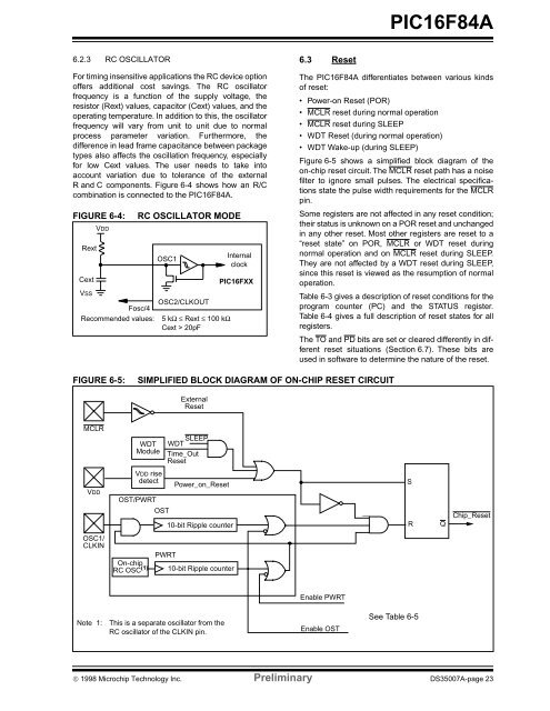
<strong>PIC16F84A</strong>6.2.3 RC OSCILLATORFor timing insensitive applications the RC device optionoffers additional cost savings. The RC oscillatorfrequency is a function of the supply voltage, theresistor (Rext) values, capacitor (Cext) values, and theoperating temperature. In addition to this, the oscillatorfrequency will vary from unit to unit due to normalprocess parameter variation. Furthermore, thedifference in lead frame capacitance between packagetypes also affects the oscillation frequency, especiallyfor low Cext values. The user needs to take intoaccount variation due to tolerance of the externalR and C components. Figure 6-4 shows how an R/Ccombination is connected to the <strong>PIC16F84A</strong>.FIGURE 6-4:RextCextVDDRC OSCILLATOR MODEOSC1VSSOSC2/CLKOUTFosc/4Recommended values: 5 kΩ ≤ Rext ≤ 100 kΩCext > 20pFInternalclockPIC16FXX6.3 ResetThe <strong>PIC16F84A</strong> differentiates between various kindsof reset:• Power-on Reset (POR)• MCLR reset during normal operation• MCLR reset during SLEEP• WDT Reset (during normal operation)• WDT Wake-up (during SLEEP)Figure 6-5 shows a simplified block diagram of theon-chip reset circuit. The MCLR reset path has a noisefilter to ignore small pulses. The electrical specificationsstate the pulse width requirements for the MCLR<strong>pin</strong>.Some registers are not affected in any reset condition;their status is unknown on a POR reset and unchangedin any other reset. Most other registers are reset to a“reset state” on POR, MCLR or WDT reset duringnormal operation and on MCLR reset during SLEEP.They are not affected by a WDT reset during SLEEP,since this reset is viewed as the resumption of normaloperation.Table 6-3 gives a description of reset conditions for theprogram counter (PC) and the STATUS register.Table 6-4 gives a full description of reset states for allregisters.The TO and PD bits are set or cleared differently in differentreset situations (Section 6.7). These bits areused in software to determine the nature of the reset.FIGURE 6-5:SIMPLIFIED BLOCK DIAGRAM OF ON-CHIP RESET CIRCUITExternalResetMCLRWDTModuleSLEEPWDTTime_OutResetVDDVDD risedetectOST/PWRTOSTPower_on_Reset10-bit Ripple counterSRQChip_ResetOSC1/CLKINOn-chipRC OSC (1)PWRT10-bit Ripple counterEnable PWRTNote 1:This is a separate oscillator from theRC oscillator of the CLKIN <strong>pin</strong>.Enable OSTSee Table 6-5© 1998 Microchip Technology Inc. Preliminary DS35007A-page 23
