PIC16F84A 18-pin Enhanced Flash/EEPROM 8-Bit MCU Data Sheet
PIC16F84A 18-pin Enhanced Flash/EEPROM 8-Bit MCU Data Sheet
PIC16F84A 18-pin Enhanced Flash/EEPROM 8-Bit MCU Data Sheet
You also want an ePaper? Increase the reach of your titles
YUMPU automatically turns print PDFs into web optimized ePapers that Google loves.
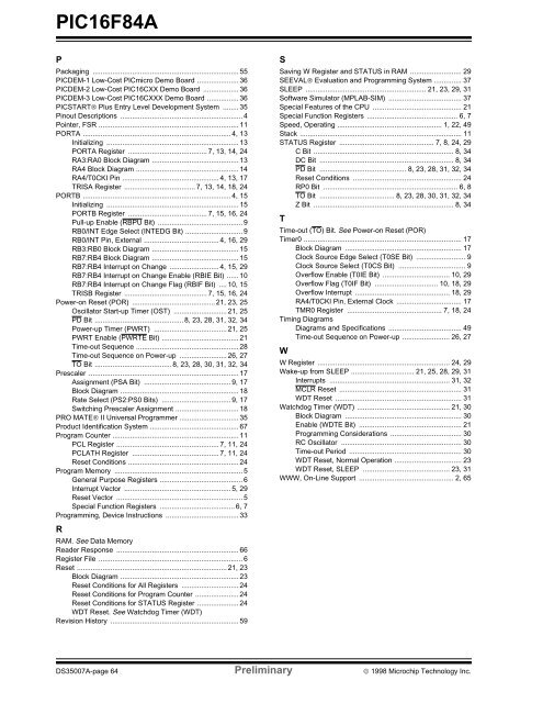
<strong>PIC16F84A</strong>PPackaging .......................................................................... 55PICDEM-1 Low-Cost PICmicro Demo Board ..................... 36PICDEM-2 Low-Cost PIC16CXX Demo Board .................. 36PICDEM-3 Low-Cost PIC16CXXX Demo Board ................ 36PICSTART® Plus Entry Level Development System ........ 35Pinout Descriptions .............................................................. 4Pointer, FSR ....................................................................... 11PORTA ........................................................................... 4, 13Initializing ................................................................... 13PORTA Register ........................................ 7, 13, 14, 24RA3:RA0 Block Diagram ............................................ 13RA4 Block Diagram .................................................... 14RA4/T0CKI Pin ................................................. 4, 13, 17TRISA Register .................................... 7, 13, 14, <strong>18</strong>, 24PORTB ........................................................................... 4, 15Initializing ................................................................... 15PORTB Register ........................................ 7, 15, 16, 24Pull-up Enable (RBPU <strong>Bit</strong>) ........................................... 9RB0/INT Edge Select (INTEDG <strong>Bit</strong>) ............................. 9RB0/INT Pin, External ...................................... 4, 16, 29RB3:RB0 Block Diagram ............................................ 15RB7:RB4 Block Diagram ............................................ 15RB7:RB4 Interrupt on Change ......................... 4, 15, 29RB7:RB4 Interrupt on Change Enable (RBIE <strong>Bit</strong>) ...... 10RB7:RB4 Interrupt on Change Flag (RBIF <strong>Bit</strong>) .... 10, 15TRISB Register .......................................... 7, 15, 16, 24Power-on Reset (POR) .......................................... 21, 23, 25Oscillator Start-up Timer (OST) ........................... 21, 25PD <strong>Bit</strong> ............................................. 8, 23, 28, 31, 32, 34Power-up Timer (PWRT) ..................................... 21, 25PWRT Enable (PWRTE <strong>Bit</strong>) ....................................... 21Time-out Sequence .................................................... 28Time-out Sequence on Power-up ........................ 26, 27TO <strong>Bit</strong> ....................................... 8, 23, 28, 30, 31, 32, 34Prescaler ............................................................................ 17Assignment (PSA <strong>Bit</strong>) ............................................ 9, 17Block Diagram ............................................................ <strong>18</strong>Rate Select (PS2:PS0 <strong>Bit</strong>s) ................................... 9, 17Switching Prescaler Assignment ................................ <strong>18</strong>PRO MATE® II Universal Programmer .............................. 35Product Identification System ............................................. 67Program Counter ................................................................ 11PCL Register .................................................... 7, 11, 24PCLATH Register ............................................ 7, 11, 24Reset Conditions ........................................................ 24Program Memory ................................................................. 5General Purpose Registers .......................................... 6Interrupt Vector ...................................................... 5, 29Reset Vector ................................................................ 5Special Function Registers ...................................... 6, 7Programming, Device Instructions ..................................... 33RRAM. See <strong>Data</strong> MemoryReader Response .............................................................. 66Register File ......................................................................... 6Reset ............................................................................ 21, 23Block Diagram ............................................................ 23Reset Conditions for All Registers ............................. 24Reset Conditions for Program Counter ...................... 24Reset Conditions for STATUS Register ..................... 24WDT Reset. See Watchdog Timer (WDT)Revision History ................................................................. 59SSaving W Register and STATUS in RAM .......................... 29SEEVAL® Evaluation and Programming System .............. 37SLEEP ............................................................. 21, 23, 29, 31Software Simulator (MPLAB-SIM) ..................................... 37Special Features of the CPU ............................................. 21Special Function Registers .............................................. 6, 7Speed, Operating ..................................................... 1, 22, 49Stack .................................................................................. 11STATUS Register ................................................ 7, 8, 24, 29C <strong>Bit</strong> ....................................................................... 8, 34DC <strong>Bit</strong> .................................................................... 8, 34PD <strong>Bit</strong> ............................................ 8, 23, 28, 31, 32, 34Reset Conditions ....................................................... 24RP0 <strong>Bit</strong> .................................................................... 6, 8TO <strong>Bit</strong> ...................................... 8, 23, 28, 30, 31, 32, 34Z <strong>Bit</strong> ....................................................................... 8, 34TTime-out (TO) <strong>Bit</strong>. See Power-on Reset (POR)Timer0 ................................................................................ 17Block Diagram ........................................................... 17Clock Source Edge Select (T0SE <strong>Bit</strong>) ......................... 9Clock Source Select (T0CS <strong>Bit</strong>) .................................. 9Overflow Enable (T0IE <strong>Bit</strong>) .................................. 10, 29Overflow Flag (T0IF <strong>Bit</strong>) ................................ 10, <strong>18</strong>, 29Overflow Interrupt ................................................ <strong>18</strong>, 29RA4/T0CKI Pin, External Clock ................................. 17TMR0 Register ................................................ 7, <strong>18</strong>, 24Timing DiagramsDiagrams and Specifications ..................................... 49Time-out Sequence on Power-up ........................ 26, 27WW Register ................................................................... 24, 29Wake-up from SLEEP ................................ 21, 25, 28, 29, 31Interrupts ............................................................. 31, 32MCLR Reset .............................................................. 31WDT Reset ................................................................ 31Watchdog Timer (WDT) ............................................... 21, 30Block Diagram ........................................................... 30Enable (WDTE <strong>Bit</strong>) .................................................... 21Programming Considerations .................................... 30RC Oscillator ............................................................. 30Time-out Period ......................................................... 30WDT Reset, Normal Operation .................................. 23WDT Reset, SLEEP ............................................ 23, 31WWW, On-Line Support ................................................ 2, 65DS35007A-page 64 Preliminary © 1998 Microchip Technology Inc.


