

PIC16F84A 18-pin Enhanced Flash/EEPROM 8-Bit MCU Data Sheet
PIC16F84A 18-pin Enhanced Flash/EEPROM 8-Bit MCU Data Sheet
PIC16F84A 18-pin Enhanced Flash/EEPROM 8-Bit MCU Data Sheet

You also want an ePaper? Increase the reach of your titles
YUMPU automatically turns print PDFs into web optimized ePapers that Google loves.
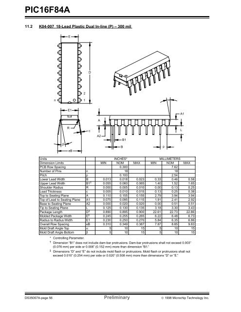
<strong>PIC16F84A</strong>11.2 K04-007 <strong>18</strong>-Lead Plastic Dual In-line (P) – 300 milED2n1αE1A1ARcLβeBA2BB1pUnits INCHES* MILLIMETERSDimension Limits MIN NOM MAX MIN NOM MAXPCB Row Spacing 0.300 7.62Number of Pins n <strong>18</strong> <strong>18</strong>Pitch p 0.100 2.54Lower Lead Width B 0.013 0.0<strong>18</strong> 0.023 0.33 0.46 0.58Upper Lead Width B1 † 0.055 0.060 0.065 1.40 1.52 1.65Shoulder Radius R 0.000 0.005 0.010 0.00 0.13 0.25Lead Thickness c 0.005 0.010 0.015 0.13 0.25 0.38Top to Seating Plane A 0.110 0.155 0.155 2.79 3.94 3.94Top of Lead to Seating Plane A1 0.075 0.095 0.115 1.91 2.41 2.92Base to Seating Plane A2 0.000 0.020 0.020 0.00 0.51 0.51Tip to Seating Plane L 0.125 0.130 0.135 3.<strong>18</strong> 3.30 3.43Package Length D ‡ 0.890 0.895 0.900 22.61 22.73 22.86Molded Package Width E ‡ 0.245 0.255 0.265 6.22 6.48 6.73Radius to Radius Width E1 0.230 0.250 0.270 5.84 6.35 6.86Overall Row Spacing eB 0.310 0.349 0.387 7.87 8.85 9.83Mold Draft Angle Top α 5 10 15 5 10 15Mold Draft Angle Bottom β 5 10 15 5 10 15* Controlling Parameter.† Dimension “B1” does not include dam-bar protrusions. Dam-bar protrusions shall not exceed 0.003”(0.076 mm) per side or 0.006” (0.152 mm) more than dimension “B1.”‡ Dimensions “D” and “E” do not include mold flash or protrusions. Mold flash or protrusions shall notexceed 0.010” (0.254 mm) per side or 0.020” (0.508 mm) more than dimensions “D” or “E.”DS35007A-page 56 Preliminary © 1998 Microchip Technology Inc.
