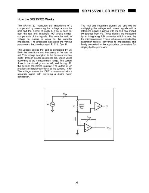
<strong>SR715</strong>/720 <strong>LCR</strong> METERHow the <strong>SR715</strong>/720 WorksThe <strong>SR715</strong>/720 measures the impedance of acomponent by measuring the voltage across thepart and the current through it. This is done forboth the real and imaginary (90° phase shifted)components of the signals. The complex ratio ofvoltage to current is equal to the compleximpedance. The processor calculates the variousparameters that are displayed, R, C, L, Q or D.The voltage across the part is generated by Vs.Both the amplitude and frequency of Vs can beset. This voltage is applied to the device under test(DUT) through source resistance Rs, which variesaccording to the measurement range. The currentflows to the virtual ground of A1, and through Rr,the current conversion resistor. The output of A1provides a signal proportional to the current, I x Rr.The voltage across the DUT is measured with aseparate signal path providing a 4-wire Kelvinconnection.The real and imaginary signals are obtained bymultiplying the voltage and current signals with areference signal in phase with Vs and one shifted90 degrees from Vs. These signals are measuredby an integrating A/D converter which is read bythe microprocessor. These values are corrected bycalibration factors, converted to impedances andfinally converted to the appropriate parameters fordisplay by the processor.xi
<strong>SR715</strong>/720 <strong>LCR</strong> METERCOMMAND LISTVARIABLES i,j Integersx Real NumberMEASUREMENT SETUP$STL(?) {i}Set (query) settling time to between i=2 and i=99 milliseconds.AVGM(?) {i}Set (query) averaging on (i=1) or off (i=0).BIAS(?) {i}Set (query) DC bias to internal (i=1), external (i=2), or off (i=0).CIRC(?) {i}Set (query) equivalent circuit to series (i=0) or parallel(i=1).CONV(?) {i}Set (query) constant voltage mode on (i=1) or off (i=0).FREQ(?) {i}Set (query) drive frequency to 100Hz(0), 120Hz(1), 1kHz(2), 10kHz(3) or 100kHz(4).MMOD(?) {i}Set (query) measurement mode to continuous (i=0) or triggered (i=1).NAVG(?) {i}Set (query) number of measurements to be averaged from i=2 to i=10.PMOD(?) {i}Set (query) parameter mode to Auto(0), R+Q(1), L+Q(2), C+D(3), or C+R(4).RATE(?) {i}Set (query) measurement rate to Fast(0), Medium(1) or Slow(2).RNGE(?) {i}Set (query) measurement range to 100kΩ(0), 6.4kΩ(1), 400Ω,(2) or 25Ω(3).RNGH(?) {i}Set (query) range hold to enabled (i=1) or disabled (i=0).VOLT(?) {x}Set (query) drive voltage to 0.1V ≤ x ≤ 1.00V with 0.05V resolution.MEASUREMENT CONTROLPREL(?) {x}Set (query) nominal parameter value for deviation and %deviation to x (Ω,F,H).STRTStarts a measurement.STOPStops the current measurement.*TRGSame as STRT.MEASUREMENT RESULTOUTF(?) {i}Set (query) the output format to verbose (0) or concise (1) ASCII, or verbose (2) orconcise (2) binary.XALL?Returns major and minor parameters plus bin number.XBIN?Returns bin number of current measurement.XDLT?Returns deviation between major parameter and nominal value.XMAJ?Returns value of the major parameter.XMIN?Returns value of the minor parameter.XPCT?Returns percent deviation between major parameter and nominal value.BINNINGBCLRClears nominal values and limits for all bins. All bins are closed.BING(?) {i}Set (query) binning to enabled (i=1) or disabled (i=0).BLIM(?) i,j {,x} Set (query) upper (i=0) or lower (i=1) limit of bin j (0-7) to x%.BNOM(?) i {,x} Set nominal value of bin i to x.SETUP CONTROL*IDN?Returns the <strong>SR715</strong>/720 identification string.*OPC(?)Set bit in Standard Event Status byte when measurement complete.*RCL i Recall setting i.*RSTReset unit to default configuration.*SAV i Save current setup as setting i.*WAIWait until all measurements are completed before proceeding.STATUS*CLSClear all status registers.*ESE(?) {i} Set (query) the Standard Event Status Byte Enable register to value i (0-255).*ESR? {i}Query Standard Status byte. If i is included, only bit i is queried.*PSC(?) {i}Set (query) power-on status clear bit to clear (i=1) or maintain (i=0) status values.*SRE(?) {i} Set (query) the Serial Poll Enable register to value i (0-255).*STB? {i}Query Serial Poll status byte. If i is included, only bit i is queried.xii