

Model SR715 Model SR720 LCR Meters
Model SR715 Model SR720 LCR Meters
Model SR715 Model SR720 LCR Meters
- No tags were found...

You also want an ePaper? Increase the reach of your titles
YUMPU automatically turns print PDFs into web optimized ePapers that Google loves.
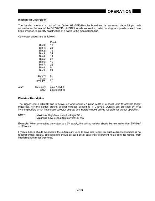
OPERATIONMechanical Description:The handler interface is part of the Option 01 GPIB/Handler board and is accessed via a 25 pin maleconnector on the rear of the <strong>SR720</strong>/715. A DB25 female connector, metal housing, and plastic sheath havebeen provided to simplify construction of a cable to the external handler.Connector pinouts are as follows:Pin #Bin 0: 13Bin 1: 25Bin 2: 12Bin 3: 24Bin 4: 11Bin 5: 23Bin 6: 10Bin 7: 22Bin 8: 9Bin 9: 21-BUSY: 8-BDA: 20-START: 3Also: +5 supply pins 7 and 19GND pins 6 and 18Electrical Description:The trigger input (-START) line is active low and requires a pulse width of at least 50ns to activate (edgetriggered).1N4148 diodes protect against voltages exceeding TTL levels. Outputs are provided by 7406inverting buffers which have open-collector outputs and therefore need pull-up resistors for proper operation.NOTE:Maximum High-level output voltage: 30 VMaximum Low-level output current: 40 mAExample: When connecting the output to a 5V supply, the pull-up resistor should be no smaller than 5V/40mA= 125 ohms.Flyback diodes should be added if the outputs are used to drive relay coils, but such a direct connection is notrecommended. Ideally, opto-isolators should be used on all data lines to prevent noise from the handler frominterfering with measurements.2-23


