Model SR715 Model SR720 LCR Meters
Model SR715 Model SR720 LCR Meters
Model SR715 Model SR720 LCR Meters
- No tags were found...
You also want an ePaper? Increase the reach of your titles
YUMPU automatically turns print PDFs into web optimized ePapers that Google loves.
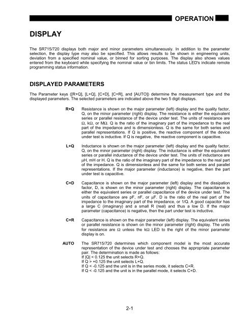
OPERATIONDISPLAYThe <strong>SR715</strong>/720 displays both major and minor parameters simultaneously. In addition to the parameterselection, the display type may also be specified. This allows results to be shown in engineering units,deviation from a specified nominal value, or binned for sorting purposes. The display also shows valuesentered from the keyboard while specifying the nominal value or bin limits. The status LED's indicate remoteprogramming status information.DISPLAYED PARAMETERSThe Parameter keys ([R+Q], [L+Q], [C+D], [C+R], and [AUTO]) determine the measurement type and thedisplayed parameters. The selected parameters are indicated above the two 5 digit displays.R+QL+QC+DC+RAUTOResistance is shown on the major parameter (left) display and the quality factor,Q, on the minor parameter (right) display. The resistance is either the equivalentseries or parallel resistance of the device under test. The units of resistance areΩ, kΩ, or MΩ. Q is the ratio of the imaginary part of the impedance to the realpart of the impedance and is dimensionless. Q is the same for both series andparallel representations. If Q is positive, the reactive component of the deviceunder test is inductive. If Q is negative, the reactive component is capacitive.Inductance is shown on the major parameter (left) display and the quality factor,Q, on the minor parameter (right) display. The inductance is either the equivalentseries or parallel inductance of the device under test. The units of inductance areµH, mH or H. Q is the ratio of the imaginary part of the impedance to the real partof the impedance. Q is dimensionless and the same for both series and parallelrepresentations. If the major parameter (inductance) is negative, then the partunder test is capacitive.Capacitance is shown on the major parameter (left) display and the dissipationfactor, D, is shown on the minor parameter (right) display. The capacitance iseither the equivalent series or parallel capacitance of the device under test. Theunits of capacitance are pF, nF, or µF. D is the ratio of the real part of theimpedance to the imaginary part of the impedance, or 1/Q. A good capacitor hasa large C (imaginary) and a small R (real) and thus a low D. If the majorparameter (capacitance) is negative, then the part under test is inductive.Capacitance is shown on the major parameter (left) display. The equivalent seriesor parallel resistance is shown on the minor parameter (right) display. The unitsfor resistance are Ω unless the kΩ LED to the right of the minor parameterdisplay is on.The <strong>SR715</strong>/720 determines which component model is the most accuraterepresentation of the device under test and chooses the appropriate parameterpair. The determination is made as follows:If |Q| < 0.125 the unit selects R+Q.If Q > +0.125 the unit selects L+Q.If Q < -0.125 and the unit is in the series mode, it selects C+R.If Q < -0.125 and the unit is in the parallel mode, it selects C+D.2-1


