Model SR715 Model SR720 LCR Meters
Model SR715 Model SR720 LCR Meters
Model SR715 Model SR720 LCR Meters
- No tags were found...
Create successful ePaper yourself
Turn your PDF publications into a flip-book with our unique Google optimized e-Paper software.
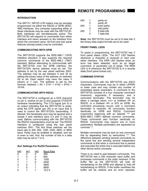
REMOTE PROGRAMMINGINTRODUCTIONThe <strong>SR715</strong> / <strong>SR720</strong> <strong>LCR</strong> meters may be remotelyprogrammed via either the RS232 or GPIB (IEEE-488) interfaces. Any computer supporting either ofthese interfaces may be used with the <strong>SR715</strong>/720.Both interfaces are simultaneously active. The<strong>SR715</strong>/720 will respond to commands from eitherinterface and return answers to the interface fromwhich the command came. All front and rear panelfeatures (except power) may be controlled.COMMUNICATING WITH GPIBThe <strong>SR715</strong>/720 supports the IEEE-488.1 (1978)interface standard. It also supports the requiredcommon commands of the IEEE-488.2 (1987)standard. Before attempting to communicate withthe <strong>SR715</strong>/720 over the GPIB interface, the<strong>SR715</strong>/720's device address must be set. Theaddress is set by the rear panel switches SW2.The address may be set between 0 and 30 bysetting the binary value of the address on switchesA0 to A4. Each switch may have the value 0(down) or 1 (up). The address is set by theformula: Address = A0 + 2*A1 + 4*A2 + 8*A3 +16*A4.COMMUNICATING WITH RS232The <strong>SR715</strong>/720 is configured as a DCE (transmiton pin 3, receive on pin 2) and supports CTS/DTRhardware handshaking. The CTS signal (pin 5) isan output indicating that the <strong>SR715</strong>/720 is ready,while the DTR signal (pin 20) is an input that isused to control the <strong>SR715</strong>/720's transmitting. Ifdesired, the handshake pins may be ignored and asimple 3 wire interface (pins 2,3 and 7) may beused. Before communicating with the <strong>SR715</strong>/720the RS232 characteristics must be set. The RS232interface is configured using the rear panelswitches SW1. The first three switches set thebaud rate to 300, 600, 1200, 2400, 4800, or 9600baud. Parity may be enabled or disabled, and setto even or odd. And, the number of bits in a databyte may be set to 7 or 8.Sw1 Settings For Rs232 Parametersbit0 bit1 bit2 Baud Rate0 0 0 3001 0 0 6000 1 0 12001 1 0 24000 0 1 48001 0 1 96000 1 1 19.2 kbit3 1 parity on0 parity offbit4 1 even parity0 odd paritybit5 1 8 data bits0 7 data bitsNote: the <strong>SR715</strong>/720 must be set to 8 data bits ifthe binary data output formats are to be used.FRONT PANEL LEDSTo assist in programming, the <strong>SR715</strong>/720 has 3front panel status LEDs. The ACT LED flasheswhenever a character is received or sent overeither interface. The ERR LED flashes when anerror has been detected, such as an illegalcommand, or parameter out of range. The REMLED is lit whenever the <strong>SR715</strong>/720 is in a remotestate (front panel locked out).COMMAND SYNTAXCommunications with the <strong>SR715</strong>/720 use ASCIIcharacters. Commands may be in either UPPERor lower case and may contain any number ofembedded space characters. A command to the<strong>SR715</strong>/720 consists of a four character commandmnemonic, arguments if necessary, and acommand terminator. The terminator may beeither a carriage return or linefeed onRS232, or a linefeed or EOI on GPIB. Nocommand processing occurs until a commandterminator is received. All commands functionidentically on GPIB and RS232. Commandmnemonics beginning with an asterisk "*" areIEEE-488.2 (1987) defined common commands.These commands also function identically onRS232. Commands may require one or moreparameters. Multiple parameters are separated bycommas ",".Multiple commands may be sent on one commandline by separating them by semicolons ";". Thedifference between sending several commands onthe same line and sending several independentcommands is that when a command line is parsedand executed the entire line is executed before anyother device action proceeds.There is no need to wait between commands. The<strong>SR715</strong>/720 has a 256 character input buffer andprocesses commands in the order received. If thebuffer fills up the <strong>SR715</strong>/720 will hold offhandshaking on the GPIB and attempt to hold offhandshaking on RS232. If the buffer overflows thebuffer will be cleared and an error reported.4-1


