

Model SR715 Model SR720 LCR Meters
Model SR715 Model SR720 LCR Meters
Model SR715 Model SR720 LCR Meters
- No tags were found...

You also want an ePaper? Increase the reach of your titles
YUMPU automatically turns print PDFs into web optimized ePapers that Google loves.
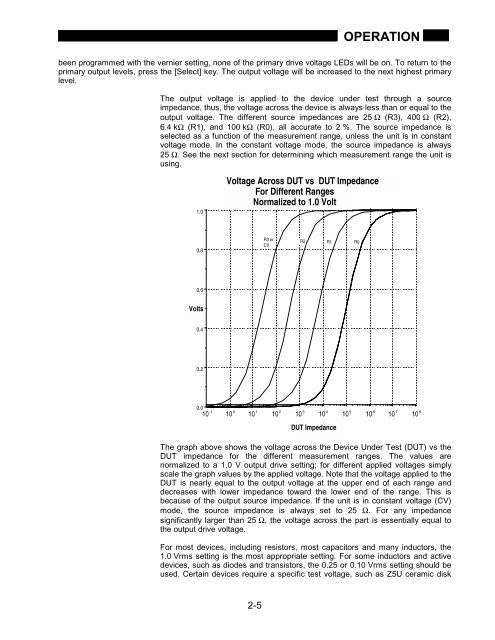
OPERATIONbeen programmed with the vernier setting, none of the primary drive voltage LEDs will be on. To return to theprimary output levels, press the [Select] key. The output voltage will be increased to the next highest primarylevel.The output voltage is applied to the device under test through a sourceimpedance, thus, the voltage across the device is always less than or equal to theoutput voltage. The different source impedances are 25 Ω (R3), 400 Ω (R2),6.4 kΩ (R1), and 100 kΩ (R0), all accurate to 2 %. The source impedance isselected as a function of the measurement range, unless the unit is in constantvoltage mode. In the constant voltage mode, the source impedance is always25 Ω. See the next section for determining which measurement range the unit isusing.1.0Voltage Across DUT vs DUT ImpedanceFor Different RangesNormalized to 1.0 Volt0.8R3 orCVR2 R1 R00.6Volts0.40.20.010 -110 010 110 210 310 410 510 610 710 8DUT ImpedanceThe graph above shows the voltage across the Device Under Test (DUT) vs theDUT impedance for the different measurement ranges. The values arenormalized to a 1.0 V output drive setting; for different applied voltages simplyscale the graph values by the applied voltage. Note that the voltage applied to theDUT is nearly equal to the output voltage at the upper end of each range anddecreases with lower impedance toward the lower end of the range. This isbecause of the output source impedance. If the unit is in constant voltage (CV)mode, the source impedance is always set to 25 Ω. For any impedancesignificantly larger than 25 Ω, the voltage across the part is essentially equal tothe output drive voltage.For most devices, including resistors, most capacitors and many inductors, the1.0 Vrms setting is the most appropriate setting. For some inductors and activedevices, such as diodes and transistors, the 0.25 or 0.10 Vrms setting should beused. Certain devices require a specific test voltage, such as Z5U ceramic disk2-5


