

Model SR715 Model SR720 LCR Meters
Model SR715 Model SR720 LCR Meters
Model SR715 Model SR720 LCR Meters
- No tags were found...

You also want an ePaper? Increase the reach of your titles
YUMPU automatically turns print PDFs into web optimized ePapers that Google loves.
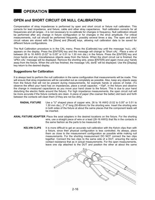
OPERATIONOPEN and SHORT CIRCUIT OR NULL CALIBRATIONCompensation of stray impedances is performed by open and short circuit or fixture null calibration. Thiscorrects for lead impedance, and fixture, cable and other stray capacitance. Null calibration corrects for allfrequencies and all ranges - it is not necessary to re-calibrate for changes in frequency. Null calibration shouldbe performed after any change in fixture configuration or for changes in the drive amplitude. For criticalmeasurements, null cal should be performed frequently, possibly several times a day. The open and shortcircuit values are stored with the [Store] and [Recall] keys, allowing null calibration data to be saved fordifferent fixture configurations.The Null Calibration procedure is in the CAL menu. Press the [Calibrate] key until the message 'nuLL cAL'appears on the display. Press the [ENTER] key and the message will change to 'Short cAL'. Place a wire ofbetween 26 to 16 AWG (0.02" to 0.05" or 0.51 to 1.30 mm dia.) in the fixture. Press the [ENTER] key andmove hands and any miscellaneous objects away from the fixture. When the short circuit cal is finished, the'oPEn cAL' message will be displayed. Remove the shorting wire, press [ENTER] and again move your handsaway from the fixture. When the unit has finished, the message 'cAL donE' will be displayed. Use the [Display]key return to the desired display.Suggestions for CalibrationIt is always best to perform the null calibration in the same configuration that measurements will be made. Thiswill ensure that stray impedances will be cancelled out as completely as possible. Also, keep any objects awayfrom the fixture that will not be present during measurements, for example hands or pieces of metal. (Toobserve the effect your hand has on impedances, place a small capacitor, ~10pF, in the fixture and observethe change in measured capacitance as you move your hand closer to the fixture. This is due to your handdisturbing the electric fields around the fixture). For high impedance measurements, the open circuit null willbe more accurate if the fixture contacts are clean. A piece of paper (the coarser the better) slid back and forthbetween the contacts will clean them (if they are not too dirty).RADIAL FIXTUREUse a "U" shaped piece of copper wire, 26 to 16 AWG (0.02 to 0.05" or 0.51 to1.30 mm dia.), 2"-3" long (50-80mm) for the shorting wire. Insert the shorting wirein both sides of the fixture at about the same places that the component leads willbe inserted.AXIAL FIXTURE ADAPTER Place the axial adapters in the desired locations on the fixture. For the shortingwire, use a straight piece of wire or a lead (26-16 AWG) that fits in the contacts inthe same fashion as the parts to be measured do.KELVIN CLIPSIt is more difficult to get an accurate null calibration with the Kelvin clips than witha fixture, since their physical configuration is less controlled. As always, placethem as close to the measurement configuration as possible while making nullmeasurements. For the shorting measurement DO NOT connect the two clipstogether. Connect the two clips to the same side of a DUT, ensuring the samecontact resistance that as in actual measurements. For the open measurements,leave one clip attached to the DUT and position the other at about the same2-16


