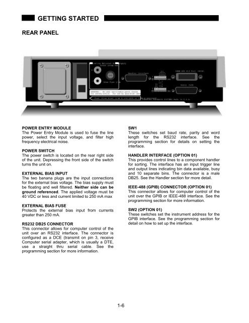
GETTING STARTEDREAR PANELPOWER ENTRY MODULEThe Power Entry Module is used to fuse the linepower, select the input voltage, and filter highfrequency electrical noise.POWER SWITCHThe power switch is located on the rear right sideof the unit. Depressing the front side of the switchturns the unit on.EXTERNAL BIAS INPUTThe two banana plugs are the input connectionsfor the external bias voltage. The bias supply mustbe floating and well filtered. Neither side can beground referenced. The applied voltage must be40 VDC or less and current limited to 250 mA maxEXTERNAL BIAS FUSEProtects the external bias input from currentsgreater than 250 mA.RS232 DB25 CONNECTORThis connector allows for computer control of theunit over an RS232 interface. The connector isconfigured as a DCE (transmit on pin 3, receiveComputer serial adapter, which is usually a DTE,use a straight thru serial cable. See theprogramming section for more information.SW1These switches set baud rate, parity and wordlength for the RS232 interface. See theprogramming section for details on setting theinterface.HANDLER INTERFACE (OPTION 01)This provides control lines to a component handlerfor sorting. The interface has an input trigger lineand output lines indicating bin data available, busyand 10 separate bins. The connector is a maleDB25. See the Handler section for more detail.IEEE-488 (GPIB) CONNECTOR (OPTION 01)This connector allows for computer control of theunit over the GPIB or IEEE-488 interface. See theprogramming section for more information.SW2 (OPTION 01)These switches set the instrument address for theGPIB interface. See the programming section fordetail on how to set up the interface.1-6
OPERATIONDISPLAYThe <strong>SR715</strong>/720 displays both major and minor parameters simultaneously. In addition to the parameterselection, the display type may also be specified. This allows results to be shown in engineering units,deviation from a specified nominal value, or binned for sorting purposes. The display also shows valuesentered from the keyboard while specifying the nominal value or bin limits. The status LED's indicate remoteprogramming status information.DISPLAYED PARAMETERSThe Parameter keys ([R+Q], [L+Q], [C+D], [C+R], and [AUTO]) determine the measurement type and thedisplayed parameters. The selected parameters are indicated above the two 5 digit displays.R+QL+QC+DC+RAUTOResistance is shown on the major parameter (left) display and the quality factor,Q, on the minor parameter (right) display. The resistance is either the equivalentseries or parallel resistance of the device under test. The units of resistance areΩ, kΩ, or MΩ. Q is the ratio of the imaginary part of the impedance to the realpart of the impedance and is dimensionless. Q is the same for both series andparallel representations. If Q is positive, the reactive component of the deviceunder test is inductive. If Q is negative, the reactive component is capacitive.Inductance is shown on the major parameter (left) display and the quality factor,Q, on the minor parameter (right) display. The inductance is either the equivalentseries or parallel inductance of the device under test. The units of inductance areµH, mH or H. Q is the ratio of the imaginary part of the impedance to the real partof the impedance. Q is dimensionless and the same for both series and parallelrepresentations. If the major parameter (inductance) is negative, then the partunder test is capacitive.Capacitance is shown on the major parameter (left) display and the dissipationfactor, D, is shown on the minor parameter (right) display. The capacitance iseither the equivalent series or parallel capacitance of the device under test. Theunits of capacitance are pF, nF, or µF. D is the ratio of the real part of theimpedance to the imaginary part of the impedance, or 1/Q. A good capacitor hasa large C (imaginary) and a small R (real) and thus a low D. If the majorparameter (capacitance) is negative, then the part under test is inductive.Capacitance is shown on the major parameter (left) display. The equivalent seriesor parallel resistance is shown on the minor parameter (right) display. The unitsfor resistance are Ω unless the kΩ LED to the right of the minor parameterdisplay is on.The <strong>SR715</strong>/720 determines which component model is the most accuraterepresentation of the device under test and chooses the appropriate parameterpair. The determination is made as follows:If |Q| < 0.125 the unit selects R+Q.If Q > +0.125 the unit selects L+Q.If Q < -0.125 and the unit is in the series mode, it selects C+R.If Q < -0.125 and the unit is in the parallel mode, it selects C+D.2-1