

Model SR715 Model SR720 LCR Meters
Model SR715 Model SR720 LCR Meters
Model SR715 Model SR720 LCR Meters
- No tags were found...

Create successful ePaper yourself
Turn your PDF publications into a flip-book with our unique Google optimized e-Paper software.
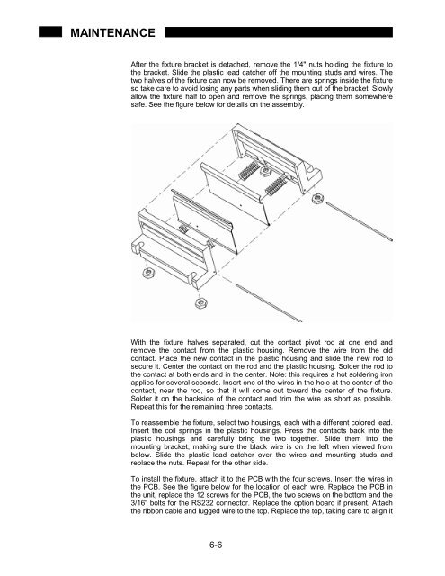
MAINTENANCEAfter the fixture bracket is detached, remove the 1/4" nuts holding the fixture tothe bracket. Slide the plastic lead catcher off the mounting studs and wires. Thetwo halves of the fixture can now be removed. There are springs inside the fixtureso take care to avoid losing any parts when sliding them out of the bracket. Slowlyallow the fixture half to open and remove the springs, placing them somewheresafe. See the figure below for details on the assembly.With the fixture halves separated, cut the contact pivot rod at one end andremove the contact from the plastic housing. Remove the wire from the oldcontact. Place the new contact in the plastic housing and slide the new rod tosecure it. Center the contact on the rod and the plastic housing. Solder the rod tothe contact at both ends and in the center. Note: this requires a hot soldering ironapplies for several seconds. Insert one of the wires in the hole at the center of thecontact, near the rod, so that it will come out toward the center of the fixture.Solder it on the backside of the contact and trim the wire as short as possible.Repeat this for the remaining three contacts.To reassemble the fixture, select two housings, each with a different colored lead.Insert the coil springs in the plastic housings. Press the contacts back into theplastic housings and carefully bring the two together. Slide them into themounting bracket, making sure the black wire is on the left when viewed frombelow. Slide the plastic lead catcher over the wires and mounting studs andreplace the nuts. Repeat for the other side.To install the fixture, attach it to the PCB with the four screws. Insert the wires inthe PCB. See the figure below for the location of each wire. Replace the PCB inthe unit, replace the 12 screws for the PCB, the two screws on the bottom and the3/16" bolts for the RS232 connector. Replace the option board if present. Attachthe ribbon cable and lugged wire to the top. Replace the top, taking care to align it6-6


