

Model SR715 Model SR720 LCR Meters
Model SR715 Model SR720 LCR Meters
Model SR715 Model SR720 LCR Meters
- No tags were found...

You also want an ePaper? Increase the reach of your titles
YUMPU automatically turns print PDFs into web optimized ePapers that Google loves.
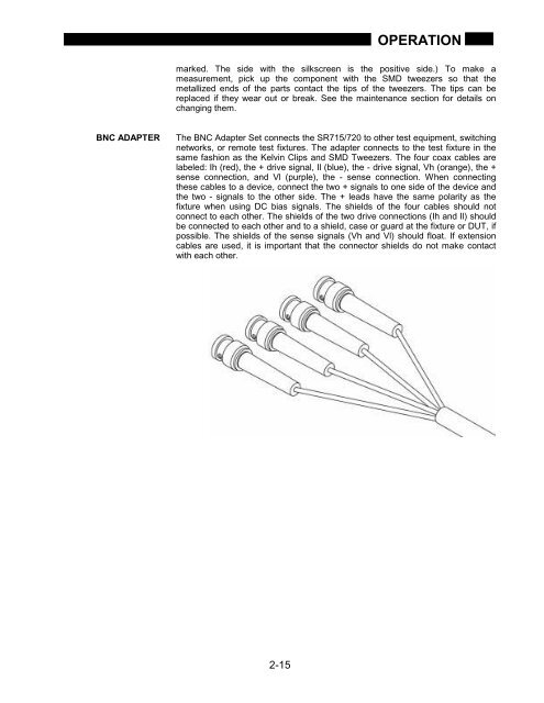
OPERATIONmarked. The side with the silkscreen is the positive side.) To make ameasurement, pick up the component with the SMD tweezers so that themetallized ends of the parts contact the tips of the tweezers. The tips can bereplaced if they wear out or break. See the maintenance section for details onchanging them.BNC ADAPTERThe BNC Adapter Set connects the <strong>SR715</strong>/720 to other test equipment, switchingnetworks, or remote test fixtures. The adapter connects to the test fixture in thesame fashion as the Kelvin Clips and SMD Tweezers. The four coax cables arelabeled: Ih (red), the + drive signal, Il (blue), the - drive signal, Vh (orange), the +sense connection, and Vl (purple), the - sense connection. When connectingthese cables to a device, connect the two + signals to one side of the device andthe two - signals to the other side. The + leads have the same polarity as thefixture when using DC bias signals. The shields of the four cables should notconnect to each other. The shields of the two drive connections (Ih and Il) shouldbe connected to each other and to a shield, case or guard at the fixture or DUT, ifpossible. The shields of the sense signals (Vh and Vl) should float. If extensioncables are used, it is important that the connector shields do not make contactwith each other.2-15


