

Model SR715 Model SR720 LCR Meters
Model SR715 Model SR720 LCR Meters
Model SR715 Model SR720 LCR Meters
- No tags were found...

Create successful ePaper yourself
Turn your PDF publications into a flip-book with our unique Google optimized e-Paper software.
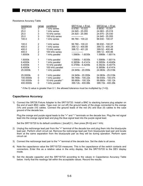
PERFORMANCE TESTSResistance Accuracy Tableresistance range conditions <strong>SR715</strong> tol. + R tol. <strong>SR720</strong> tol. + R tol.10.0 3 1 kHz series 9.9780 - 10.022 9.9930 - 10.00725.0 3 1 kHz series 24.945 - 25.055 24.983 - 25.01825.0 3 10 kHz series 24.920 - 25.080 24.970 - 25.03025.0 3 100 kHz series --------------- 24.945 - 25.055100.0 3 1 kHz series 99.780 - 100.22 99.930 - 100.07100.0 2 1 kHz series 99.780 - 100.22 99.930 - 100.07400.0 2 1 kHz series 399.12 - 400.88 399.72 - 400.28400.0 2 10 kHz series 398.72 - 401.28 399.52 - 400.48400.0 2 100 kHz series --------------- 399.12 - 400.881.6000k 2 1 kHz parallel 1.5965k - 1.6035k 1.5989k - 1.6011k1.6000k 1 1 kHz parallel 1.5965k - 1.6035k 1.5989k - 1.6011k6.4000k 1 1 kHz parallel 6.3859k - 6.4141k 6.3955k - 6.4045k6.4000k 1 10 kHz parallel 6.3795k - 6.4205k 6.3923k - 6.4077k6.4000k 1 100 kHz parallel ----------------- 6.3859k - 6.4141k25.0000k 1 1 kHz parallel 24.945k - 20.055k 24.983k - 25.018k25.0000k 0 1 kHz parallel 24.945k - 20.055k 24.983k - 25.018k100.0000k 0 1 kHz parallel 99.780k - 100.22k 99.930k - 100.07k100.0000k 0 10 kHz parallel * 99.680k - 100.32k 99.880k - 100.12k400.0000k 0 1 kHz parallel 399.12k - 400.88k 399.72k - 400.28k* if the Q value is greater than 0.1, the allowed tolerance must be multiplied by (1+Q).Capacitance Accuracy1) Connect the SR728 Fixture Adapter to the <strong>SR715</strong>/720. Install a BNC to stacking banana plug adapter onthe end of each BNC cable. Tape over (or cut off) the ground leads of the plugs connected to the orange(Vh) and purple (Vl) cables. Connect the ground leads of the red (Ih) and blue (Il) cables to the caseground of the decade box.Plug the orange and purple signal leads to the "+" and "-" terminals on the decade box. Plug the red signallead into the orange signal lead and plug the blue signal lead into the purple signal lead.Set the <strong>SR715</strong>/720 to its default conditions ( [recall] 0 ), then press [R+Q] and 1 kHz.2) Unplug the red/orange lead pair from the "+" terminal of the decade box and plug them into the blue/purplelead pair. Perform short circuit cal. Remove the red/orange lead pair from blue/purple lead pair and locatethem at the same separation from the blue/purple pair as they will be during operation. Perform opencircuit cal.3) Connect the red/orange lead pair to the "+" terminal of the decade box. Set the dials to all zeros.4) Note the capacitance value the <strong>SR715</strong>/720 measures. This is the capacitance of the switch contacts andconnectors. Enter this as a relative value in the entry display. Set the <strong>SR715</strong>/720 to the DEV displaymode.5) Set the decade capacitor and the <strong>SR715</strong>/720 according to the values in Capacitance Accuracy Tablebelow. Verify that the readings fall within the acceptable values. Record the results.5-6


