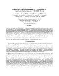
Asymmetric fluid-structure dynamics in nanoscale imprint lithography
Asymmetric fluid-structure dynamics in nanoscale imprint lithography
Asymmetric fluid-structure dynamics in nanoscale imprint lithography
- No tags were found...

You also want an ePaper? Increase the reach of your titles
YUMPU automatically turns print PDFs into web optimized ePapers that Google loves.
1.2.1 Optical Lithography Process OverviewThe <strong>in</strong>itial step is to have a semiconductor wafer sp<strong>in</strong>-coated and bakedwith an imag<strong>in</strong>g layer of photoresist. The photoresist acts as a layer ofphotosensitive organic polymers that is selectively exposed through an aerialimage of the photomask. The solubility of the photoresist is <strong>in</strong>creased (positiveresist) or decreased (negative resist) upon exposure to the illum<strong>in</strong>ation source.R<strong>in</strong>s<strong>in</strong>g the wafer <strong>in</strong> a developer solution selectively dissolves the photoresistwhile the circuit pattern rema<strong>in</strong>s on the semiconductor wafer.Central to the image transfer process <strong>in</strong> optical <strong>lithography</strong> is the exposuresystem comprised of a lithographic lens, an illum<strong>in</strong>ation source, and a waferposition<strong>in</strong>g system. The lithographic lens is a large compound lens comprised of10 to 20 simple lens elements. The lens systems of today are designed to producea typical demagnification factor of 4×. The illum<strong>in</strong>ation source is typically ahigh-pressure mercury-xenon arc lamp with undesired wavelengths removed withmulti-layer dielectric filters. The rema<strong>in</strong><strong>in</strong>g narrow-band light, with less than0.003 nm spectral width, is sent through a series of relay optics and uniformiz<strong>in</strong>goptics and is then projected through the photomask and lithographic lens [Sheatsand Smith 1998]. Figure 1.1 illustrates the optical <strong>lithography</strong> process.The circuit pattern on the quartz plate, written by electron beam<strong>lithography</strong>, conta<strong>in</strong>s the master pattern at four times the size of the imagedpattern. The imaged is reduced <strong>in</strong> size through the lithographic lens and theimag<strong>in</strong>g layer is exposed. The solubility of the photoresist is altered by thisradiation. The wafer is then r<strong>in</strong>sed <strong>in</strong> a develop<strong>in</strong>g solution to remove the highcontrastsoluble resist. The rema<strong>in</strong><strong>in</strong>g resist pattern will serve as a mask forprocesses such as metal deposition, epitaxial growth, and ion implantation [Choi,Johnson, and Sreenivasan 1999].4