Asymmetric fluid-structure dynamics in nanoscale imprint lithography
Asymmetric fluid-structure dynamics in nanoscale imprint lithography
Asymmetric fluid-structure dynamics in nanoscale imprint lithography
- No tags were found...

Create successful ePaper yourself
Turn your PDF publications into a flip-book with our unique Google optimized e-Paper software.
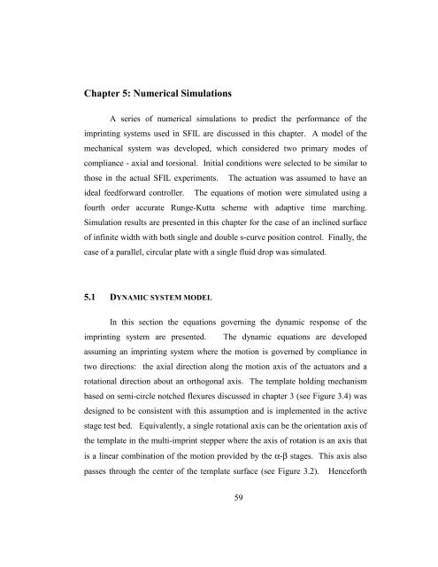
Chapter 5: Numerical SimulationsA series of numerical simulations to predict the performance of theimpr<strong>in</strong>t<strong>in</strong>g systems used <strong>in</strong> SFIL are discussed <strong>in</strong> this chapter. A model of themechanical system was developed, which considered two primary modes ofcompliance - axial and torsional. Initial conditions were selected to be similar tothose <strong>in</strong> the actual SFIL experiments. The actuation was assumed to have anideal feedforward controller. The equations of motion were simulated us<strong>in</strong>g afourth order accurate Runge-Kutta scheme with adaptive time march<strong>in</strong>g.Simulation results are presented <strong>in</strong> this chapter for the case of an <strong>in</strong>cl<strong>in</strong>ed surfaceof <strong>in</strong>f<strong>in</strong>ite width with both s<strong>in</strong>gle and double s-curve position control. F<strong>in</strong>ally, thecase of a parallel, circular plate with a s<strong>in</strong>gle <strong>fluid</strong> drop was simulated.5.1 DYNAMIC SYSTEM MODELIn this section the equations govern<strong>in</strong>g the dynamic response of theimpr<strong>in</strong>t<strong>in</strong>g system are presented. The dynamic equations are developedassum<strong>in</strong>g an impr<strong>in</strong>t<strong>in</strong>g system where the motion is governed by compliance <strong>in</strong>two directions: the axial direction along the motion axis of the actuators and arotational direction about an orthogonal axis. The template hold<strong>in</strong>g mechanismbased on semi-circle notched flexures discussed <strong>in</strong> chapter 3 (see Figure 3.4) wasdesigned to be consistent with this assumption and is implemented <strong>in</strong> the activestage test bed. Equivalently, a s<strong>in</strong>gle rotational axis can be the orientation axis ofthe template <strong>in</strong> the multi-impr<strong>in</strong>t stepper where the axis of rotation is an axis thatis a l<strong>in</strong>ear comb<strong>in</strong>ation of the motion provided by the α-β stages. This axis alsopasses through the center of the template surface (see Figure 3.2). Henceforth59