Asymmetric fluid-structure dynamics in nanoscale imprint lithography
Asymmetric fluid-structure dynamics in nanoscale imprint lithography
Asymmetric fluid-structure dynamics in nanoscale imprint lithography
- No tags were found...

Create successful ePaper yourself
Turn your PDF publications into a flip-book with our unique Google optimized e-Paper software.
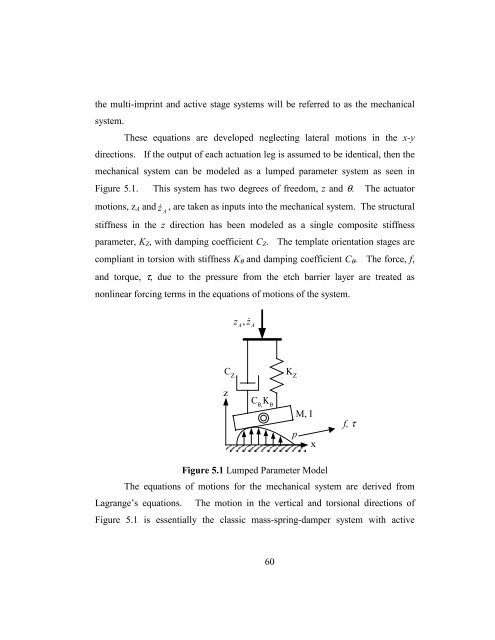
the multi-impr<strong>in</strong>t and active stage systems will be referred to as the mechanicalsystem.These equations are developed neglect<strong>in</strong>g lateral motions <strong>in</strong> the x-ydirections. If the output of each actuation leg is assumed to be identical, then themechanical system can be modeled as a lumped parameter system as seen <strong>in</strong>Figure 5.1.This system has two degrees of freedom, z and θ. The actuatormotions, z A and z A, are taken as <strong>in</strong>puts <strong>in</strong>to the mechanical system. The structuralstiffness <strong>in</strong> the z direction has been modeled as a s<strong>in</strong>gle composite stiffnessparameter, K Z , with damp<strong>in</strong>g coefficient C Z . The template orientation stages arecompliant <strong>in</strong> torsion with stiffness K θ and damp<strong>in</strong>g coefficient C θ . The force, f,and torque, τ, due to the pressure from the etch barrier layer are treated asnonl<strong>in</strong>ear forc<strong>in</strong>g terms <strong>in</strong> the equations of motions of the system.z, DAz AC ZzC θ,Κ θK ZM, Ipxf, τFigure 5.1 Lumped Parameter ModelThe equations of motions for the mechanical system are derived fromLagrange’s equations. The motion <strong>in</strong> the vertical and torsional directions ofFigure 5.1 is essentially the classic mass-spr<strong>in</strong>g-damper system with active60