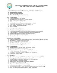
View File - University of Engineering and Technology, Taxila
View File - University of Engineering and Technology, Taxila
View File - University of Engineering and Technology, Taxila

You also want an ePaper? Increase the reach of your titles
YUMPU automatically turns print PDFs into web optimized ePapers that Google loves.
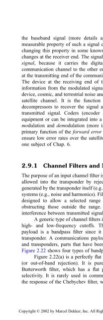
the baseb<strong>and</strong> signal (more details appear in Chap. 3, Sec. 3.2.4). Anymeasurable property <strong>of</strong> such a signal can be used to transmit information bychanging this property in some known manner <strong>and</strong> then detecting whateverchanges at the receiver end. The signal that is modulated is called the carriersignal, because it carries the digital information from one end <strong>of</strong> thecommunication channel to the other end. The device that changes the signalat the transmitting end <strong>of</strong> the communication channel is called the modulator.The device at the receiving end <strong>of</strong> the channel, which detects the digitalinformation from the modulated signal, is called the demodulator. Thermal,device, cosmic, <strong>and</strong> terrestrial noise <strong>and</strong> other satellite interference corrupt thesatellite channel. It is the function <strong>of</strong> the demodulators, decoders, <strong>and</strong>decompressors to recover the signal <strong>and</strong> produce the desired replica <strong>of</strong> thetransmitted signal. Coders (encoder <strong>and</strong> decoders) can be as st<strong>and</strong>aloneequipment or can be integrated into a modularized modem: a contraction <strong>of</strong>modulation <strong>and</strong> demodulation (more is said <strong>of</strong> modems in Sec. 3.3.1). Theprimary function <strong>of</strong> the forward error correction (FEC) coding method is toensure low error rates over the satellite link. Error correction techniques areone subject <strong>of</strong> Chap. 6.2.9.1 Channel Filters <strong>and</strong> MultiplexersThe purpose <strong>of</strong> an input channel filter is to confine the b<strong>and</strong>width <strong>of</strong> the signalallowed into the transponder by rejecting unwanted signals such as thosegenerated by the transponder itself (e.g., spurii) <strong>and</strong> from other communicationsystems (e.g., noise <strong>and</strong> harmonics). Filters are electrical or microwave devicesdesigned to allow a selected range <strong>of</strong> signal frequencies to pass whileobstructing those outside the range. They also reduce the possibility <strong>of</strong>interference between transmitted signals.A generic type <strong>of</strong> channel filters is the b<strong>and</strong>pass filter—a filter with bothhigh- <strong>and</strong> low-frequency cut<strong>of</strong>fs. The channel filter in communicationspayload is a b<strong>and</strong>pass filter since it defines the usable b<strong>and</strong>width <strong>of</strong> thetransponder. A communications payload is divided into two parts: antennas<strong>and</strong> transponders, parts that have been previously discussed in this chapter.Figure 2.22 shows four types <strong>of</strong> b<strong>and</strong>pass filters.Figure 2.22(a) is a perfectly flat passb<strong>and</strong> filter with infinite selectivity(or out-<strong>of</strong>-b<strong>and</strong> rejection). It is purely theoretical. Figure 2.22(b) is theButterworth filter, which has a flat passb<strong>and</strong> with slow roll<strong>of</strong>f <strong>and</strong> poorselectivity. It is rarely used in communications payloads. Figure 2.22(c) isthe response <strong>of</strong> the Chebychev filter, which solves the selectivity problems atCopyright © 2002 by Marcel Dekker, Inc. All Rights Reserved.