- Page 2:
SatelliteCommunicationEngineeringMi
- Page 6:
This book is dedicated to my famili
- Page 10:
Because of the immense importance o
- Page 14:
means of a combination of applicati
- Page 18:
about my promise to my students, an
- Page 22:
2.3 Coverage Area and Satellite Net
- Page 26:
1Basic Principles of SatelliteCommu
- Page 30:
and voice (telephone) communication
- Page 34:
FIGURE 1.2Communication between two
- Page 38:
interpreting or uncovering the deci
- Page 42:
cryptographic keys K ti (where i ¼
- Page 46:
FIGURE 1.6Block ciphering technique
- Page 50:
FIGURE 1.7Part of block ciphering w
- Page 54:
Based on the ordering sequence of (
- Page 58:
TABLE 1.1 (continued )S612 1 10 15
- Page 62:
For an uncoded message x and the fe
- Page 66:
2. Your task is to develop a commun
- Page 70:
FIGURE 2.1Geometry of a satellite.
- Page 74:
Future trends in satellite antennas
- Page 78:
In the United States, the three sat
- Page 82:
TABLE 2.3Typical Links Frequency Ba
- Page 86:
FIGURE 2.4Satellite period and orbi
- Page 90:
FIGURE 2.6An illustration of covera
- Page 94:
FIGURE 2.7constellation.A sketch of
- Page 98:
width of 1:73 with reduced coverag
- Page 102:
y ¼ elevation angle of satellite f
- Page 106:
We can conclude that the antenna mu
- Page 110:
FIGURE 2.9Design flowchart of a sat
- Page 114:
Risk control and monitoring measure
- Page 118:
TABLE 2.4Antenna Selection Criteria
- Page 122:
Then the system availability can be
- Page 126:
In fact, MTBF is the reciprocal of
- Page 130:
2.7 ANTENNASBased on function, sate
- Page 134:
Two kinds of horns in common use ar
- Page 138:
FIGURE 2.13Geometry of a parabolic
- Page 142:
FIGURE 2.14 Axisymmetric reflector
- Page 146:
A transceiver antenna is a single a
- Page 150:
The gain, in the axial mode, of a h
- Page 154:
angles, spacecraft may shadow the s
- Page 158:
3. The probability of both parallel
- Page 162:
the baseband signal (more details a
- Page 166:
matrix in the communications subsys
- Page 170:
FIGURE 2.24Typical transfer charact
- Page 174:
4. Iridium LCC (1997). Iridium Syst
- Page 178:
3Earth StationsIn Chap. 2 we discus
- Page 182:
The most popular forms of modulatio
- Page 186:
Small earth stations are antennas w
- Page 190:
FIGURE 3.2BPSK space diagram.Instea
- Page 194:
OQPSKOffset QPSK (OQPSK) is a modif
- Page 198:
FIGURE 3.7An 8-PSK space diagram.an
- Page 202:
aud. The word ‘‘baud’’ hono
- Page 206:
Noise power density N 0bandwidth:N
- Page 210:
We observe in (3.11) that E b =N 0
- Page 214:
to (3.23) shows that a margin of 11
- Page 218:
FIGURE 3.12 Principle of scrambling
- Page 222:
Equalization FilterAn equalization
- Page 226:
that is, N zeros at the top and bot
- Page 230:
Example 3.2: Consider a transmissio
- Page 234:
which can be written as89>=R xy ðt
- Page 238:
ecause a voice signal is usually hi
- Page 242:
systems is discussed in Sec. 4.2. O
- Page 246:
where T e is the equivalent tempera
- Page 250:
operating principle of all directio
- Page 254:
performance of the satellite commun
- Page 258:
3. For two independent sources, wit
- Page 262:
FIGURE 3.21 A representation of mut
- Page 266:
In practice, Eqs. (3.78) and (3.76)
- Page 270:
This condition is always satisfied
- Page 274:
Copyright © 2002 by Marcel Dekker,
- Page 278:
epeaters overshooting into subseque
- Page 282:
6. Conventional BPSK modulation all
- Page 286:
4Satellite LinksA satellite link co
- Page 290:
FIGURE 4.2 Basic antenna parameters
- Page 294:
For unity efficiency, and substitut
- Page 298:
This expression neglects losses oth
- Page 302:
This expression is equally valid fo
- Page 306:
and Lin [5]:whereL ¼L o1 þ L oðr
- Page 310:
3. Calculate attenuation A r in dB
- Page 314:
4.2.1 Intersatellite LinksAs indica
- Page 318:
We know from (4.4b) that f c is dep
- Page 322:
FIGURE 4.9 Cross-link transmission
- Page 326:
Follow the uplink procedure for the
- Page 330:
Satellite:Frequencies:14.75 GHz up
- Page 334:
6. For link to be maintained betwee
- Page 338:
5.1 PRINCIPLES OF MULTIPLE ACCESSAs
- Page 342:
neously, their transmissions collid
- Page 346:
technique and would remain the most
- Page 350:
FIGURE 5.4 Typical TDMA frame struc
- Page 354: FIGURE 5.6TDMA throughput for an IN
- Page 358: and transmits through the satellite
- Page 362: FIGURE 5.8FDMA total capacity respo
- Page 366: tion; that is, log e ð1 þ xÞ x t
- Page 370: REFERENCES1. Spilker, J.J. (1977).
- Page 374: 6.1 CHANNEL CODINGNoise within a tr
- Page 378: where G is a generator matrix that
- Page 382: The syndrome is a single word of le
- Page 386: SolutionComparing (i) and (ii) with
- Page 390: Cyclic CodesCyclic codes are a subs
- Page 394: When errors occur in bursts, the nu
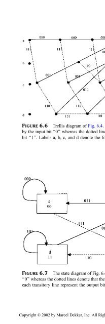
- Page 398: FIGURE 6.3Rate 1/2 convolutional en
- Page 402: us to a particular node in the tree
- Page 408: FIGURE 6.8 Code tree diagram of rat
- Page 412: consistent with the constraint leng
- Page 416: trellis depth is approximated to 5L
- Page 420: FIGURE P.1A convolutional coder.the
- Page 424: 7Regulatory Agencies andProceduresT
- Page 428: of the radiofrequency spectrum, and
- Page 432: The CCIR works through the medium o
- Page 436: 7.1.3 IFRBThe International Frequen
- Page 440: The national or regional spectrum m
- Page 444: 3. The need to expand or enhance th
- Page 448: The DSP will be responsible for res
- Page 452: 2. Provide a convenient framework w
- Page 456:
FIGURE 8.3Types of user-to-network
- Page 460:
H1-channels are designed to carry v
- Page 464:
information. The transfer cell prov
- Page 468:
The OSI layers are divided into two
- Page 472:
plane is denoted by U, the control
- Page 476:
interfacing, maintenance, and conne
- Page 480:
adjoining base station to scan the
- Page 484:
FIGURE 8.9Geometry of a polygon.The
- Page 488:
FIGURE 8.11Splitting cells into sma
- Page 492:
causes signal fading. Of course, th
- Page 496:
FIGURE 8.14TCP=IP suite and its rel
- Page 500:
access to an Internet point of pres
- Page 504:
message security via satellite is d
- Page 508:
REFERENCES1. Wu, W.W. (1989). Eleme
- Page 512:
Appendix ANotationsThe symbols have
- Page 516:
N sPP rP sP TRRðtÞR cR eR rR vSS
- Page 520:
g Central anglez Channel gainZ Ante
- Page 524:
AttenuationBandwidthBearer serviceB
- Page 528:
Frequency divisionmultiple accessFr
- Page 532:
MultiplexingNetworkOmnidirectionala
- Page 536:
UplinkUser-to-networkinterfaceThe e