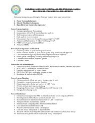
View File - University of Engineering and Technology, Taxila
View File - University of Engineering and Technology, Taxila
View File - University of Engineering and Technology, Taxila

You also want an ePaper? Increase the reach of your titles
YUMPU automatically turns print PDFs into web optimized ePapers that Google loves.
The most popular forms <strong>of</strong> modulation used in digital communications arebinary phase shift keying (BPSK), quadrature phase shift keying (QPSK),<strong>of</strong>fset-quadrature phase shift keying (OQPSK), <strong>and</strong> 8-PSK. These modulationformats can be described in a general form as M-PSK modulation, whereM ¼ 2 b bits, each symbol represents b bits, <strong>and</strong> b is an integer, 1, 2, or 3. Thegeneralized M-PSK is discussed in Sec. 3.2.A modem converts a digital signal to an analog tone (modulation) <strong>and</strong>reconverts the analog tone (demodulation) into its original digital signal at theother side <strong>of</strong> connection (modems are described in Sec. 3.3.1). Both amplitude-modulation(AM) <strong>and</strong> frequency-modulation (FM) techniques are examples<strong>of</strong> analog-type or uncoded signal-transmission systems with one-to-onecorrespondence between the input signal <strong>and</strong> the modulated carrier eventuallytransmitted.The reader might ask, why code? A coded system makes much moreefficient use <strong>of</strong> b<strong>and</strong>width widening to increase the output signal-to-noise ratiothan does an uncoded system. Coded systems are inherently capable <strong>of</strong> bettertransmission efficiency than the uncoded types.A general division may be made to classify frequency division multiplexing(FDM) voice <strong>and</strong> video signals to use FM while classifying digitallymultiplexed voice <strong>and</strong> data to use some form <strong>of</strong> phase modulation.In the receiving chain, the received signals pass through a sequence <strong>of</strong>processing steps that are essentially the reverse <strong>of</strong> those followed to preparethe outgoing signals. The RF received signals are passed through a low-noisewideb<strong>and</strong> RF front end, followed by a translator to IF. It is at the IF stage thatthe specific uplink carriers hoping to be received are separated <strong>and</strong> grouped bydestination, then demodulated to their original baseb<strong>and</strong> signals followed byan FEC decoder (in the case <strong>of</strong> digital satellite communications). Those notspecifically destined to the earth station are retransmitted, thereby acting like atransponder. The demodulated baseb<strong>and</strong> signals may then be demultiplexed, ifnecessary, <strong>and</strong> thereby transferred to the users.The antenna in Fig. 3.1 is used for transmitting <strong>and</strong> receiving: this typeis called a transceiver. The basic principles <strong>and</strong> characteristics <strong>of</strong> antennashave been discussed in Chap. 2, Sec. 2.7; they also apply to the earth stationantennas. However, in addition to the antenna characteristics discussed in Sec.2.7, the antenna subsystem requires separate tracking equipment, whichensures precise pointing <strong>of</strong> the antenna at the satellite. With small earthstations where the antenna’s b<strong>and</strong>width is large, precision-tracking equipmentis not necessary. The antenna tracking system can be programmed to point topreassigned direction(s) automatically <strong>and</strong> can also be directed manually. Wediscuss more on antenna tracking systems in Sec. 3.4.2.Copyright © 2002 by Marcel Dekker, Inc. All Rights Reserved.