Processor Local Bus Functional Model Toolkit User's Manual
Processor Local Bus Functional Model Toolkit User's Manual
Processor Local Bus Functional Model Toolkit User's Manual

You also want an ePaper? Increase the reach of your titles
YUMPU automatically turns print PDFs into web optimized ePapers that Google loves.
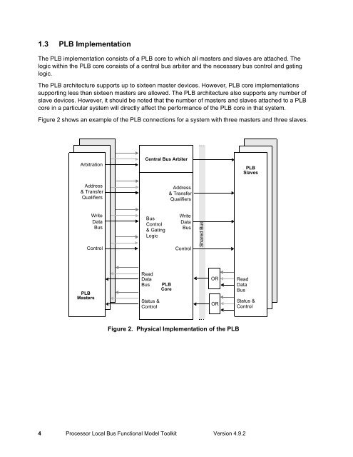
1.3 PLB Implementation<br />
The PLB implementation consists of a PLB core to which all masters and slaves are attached. The<br />
logic within the PLB core consists of a central bus arbiter and the necessary bus control and gating<br />
logic.<br />
The PLB architecture supports up to sixteen master devices. However, PLB core implementations<br />
supporting less than sixteen masters are allowed. The PLB architecture also supports any number of<br />
slave devices. However, it should be noted that the number of masters and slaves attached to a PLB<br />
core in a particular system will directly affect the performance of the PLB core in that system.<br />
Figure 2 shows an example of the PLB connections for a system with three masters and three slaves.<br />
Arbitration<br />
Address<br />
& Transfer<br />
Qualifiers<br />
Write<br />
Data<br />
<strong>Bus</strong><br />
Control PLB<br />
PLB<br />
Master 1<br />
PLB<br />
Masters<br />
Central <strong>Bus</strong> Arbiter<br />
<strong>Bus</strong><br />
Control<br />
& Gating<br />
Logic<br />
Read<br />
Data<br />
<strong>Bus</strong><br />
Status &<br />
Control<br />
PLB<br />
Core<br />
Address<br />
& Transfer<br />
Qualifiers<br />
Write<br />
Data<br />
<strong>Bus</strong><br />
Control<br />
4 <strong>Processor</strong> <strong>Local</strong> <strong>Bus</strong> <strong>Functional</strong> <strong>Model</strong> <strong>Toolkit</strong> Version 4.9.2<br />
Shared <strong>Bus</strong><br />
OR<br />
OR<br />
Figure 2. Physical Implementation of the PLB<br />
PLB<br />
Slaves<br />
Read<br />
Data <strong>Bus</strong><br />
<strong>Bus</strong><br />
Status &<br />
Status Control &<br />
Control