

Design Challenges: Avoiding the Pitfalls, winning the game - Xilinx
Design Challenges: Avoiding the Pitfalls, winning the game - Xilinx
Design Challenges: Avoiding the Pitfalls, winning the game - Xilinx

Create successful ePaper yourself
Turn your PDF publications into a flip-book with our unique Google optimized e-Paper software.
Versatile FPGA Power Solutions from National Semiconductor<br />
LM2743/44 Low-Voltage Synchronous Buck Controllers<br />
3V to 6V<br />
(Bias)<br />
ON<br />
OFF<br />
Output power good<br />
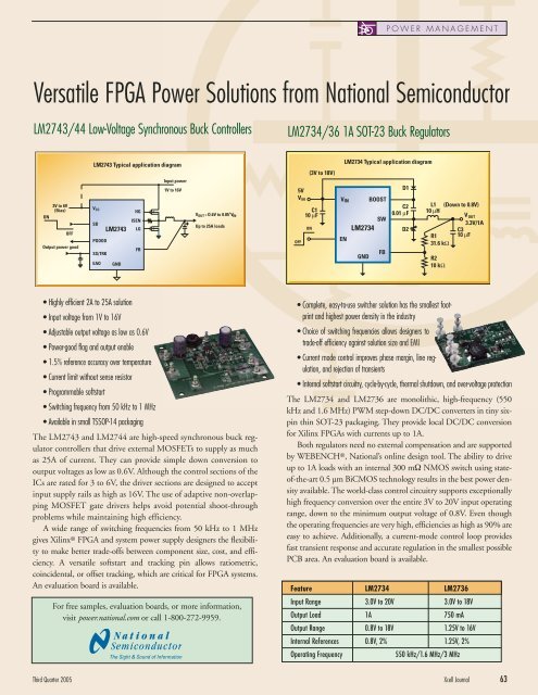
LM2743 Typical application diagram<br />
V CC<br />
SD<br />
PGOOD<br />
LM2743<br />
SS/TRK<br />
EAO GND<br />
HG<br />
ISEN<br />
LG<br />
FB<br />
Input power<br />
1V to 16V<br />
V OUT = O.6V to 0.85 *V IN<br />
Up to 25A loads<br />
• Highly efficient 2A to 25A solution<br />
• Input voltage from 1V to 16V<br />
• Adjustable output voltage as low as 0.6V<br />
• Power-good flag and output enable<br />
• 1.5% reference accuracy over temperature<br />
• Current limit without sense resistor<br />
• Programmable softstart<br />
• Switching frequency from 50 kHz to 1 MHz<br />
• Available in small TSSOP-14 packaging<br />
The LM2743 and LM2744 are high-speed synchronous buck regulator<br />
controllers that drive external MOSFETs to supply as much<br />
as 25A of current. They can provide simple down conversion to<br />
output voltages as low as 0.6V. Although <strong>the</strong> control sections of <strong>the</strong><br />
ICs are rated for 3 to 6V, <strong>the</strong> driver sections are designed to accept<br />
input supply rails as high as 16V. The use of adaptive non-overlapping<br />
MOSFET gate drivers helps avoid potential shoot-through<br />
problems while maintaining high efficiency.<br />
A wide range of switching frequencies from 50 kHz to 1 MHz<br />
gives <strong>Xilinx</strong> ® FPGA and system power supply designers <strong>the</strong> flexibility<br />
to make better trade-offs between component size, cost, and efficiency.<br />
A versatile softstart and tracking pin allows ratiometric,<br />
coincidental, or offset tracking, which are critical for FPGA systems.<br />
An evaluation board is available.<br />
For free samples, evaluation boards, or more information,<br />
visit power.national.com or call 1-800-272-9959.<br />
• Complete, easy-to-use switcher solution has <strong>the</strong> smallest footprint<br />
and highest power density in <strong>the</strong> industry<br />
• Choice of switching frequencies allows designers to<br />
trade-off efficiency against solution size and EMI<br />
• Current mode control improves phase margin, line regulation,<br />
and rejection of transients<br />
• Internal softstart circuitry, cycle-by-cycle, <strong>the</strong>rmal shutdown, and over-voltage protection<br />
The LM2734 and LM2736 are monolithic, high-frequency (550<br />
kHz and 1.6 MHz) PWM step-down DC/DC converters in tiny sixpin<br />
thin SOT-23 packaging. They provide local DC/DC conversion<br />
for <strong>Xilinx</strong> FPGAs with currents up to 1A.<br />
Both regulators need no external compensation and are supported<br />
by WEBENCH ®, National’s online design tool. The ability to drive<br />
up to 1A loads with an internal 300 mΩ NMOS switch using stateof-<strong>the</strong>-art<br />
0.5 µm BiCMOS technology results in <strong>the</strong> best power density<br />
available. The world-class control circuitry supports exceptionally<br />
high frequency conversion over <strong>the</strong> entire 3V to 20V input operating<br />
range, down to <strong>the</strong> minimum output voltage of 0.8V. Even though<br />
<strong>the</strong> operating frequencies are very high, efficiencies as high as 90% are<br />
easy to achieve. Additionally, a current-mode control loop provides<br />
fast transient response and accurate regulation in <strong>the</strong> smallest possible<br />
PCB area. An evaluation board is available.<br />
Third Quarter 2005 Xcell Journal 63<br />
5V<br />
VIN<br />
OFF<br />
C1<br />
10 µF<br />
ON<br />
(3V to 18V)<br />
LM2734 Typical application diagram<br />
VIN<br />
EN<br />
SW<br />
LM2734<br />
GND<br />
BOOST<br />
FB<br />
POWER MANAGEMENT<br />
LM2734/36 1A SOT-23 Buck Regulators<br />
D1<br />
C2<br />
0.01 µF<br />
D2<br />
L1<br />
10 µH<br />
R1<br />
31.6 kΩ<br />
R2<br />
10 kΩ<br />
(Down to 0.8V)<br />
V OUT<br />
3.3V/1A<br />
C3<br />
10 µF<br />
Feature LM2734 LM2736<br />
Input Range 3.0V to 20V 3.0V to 18V<br />
Output Load 1A 750 mA<br />
Output Range 0.8V to 18V 1.25V to 16V<br />
Internal References 0.8V, 2% 1.25V, 2%<br />
Operating Frequency 550 kHz/1.6 MHz/3 MHz


