Installation & Operation Manual - StellarSupport - John Deere
Installation & Operation Manual - StellarSupport - John Deere
Installation & Operation Manual - StellarSupport - John Deere

Create successful ePaper yourself
Turn your PDF publications into a flip-book with our unique Google optimized e-Paper software.
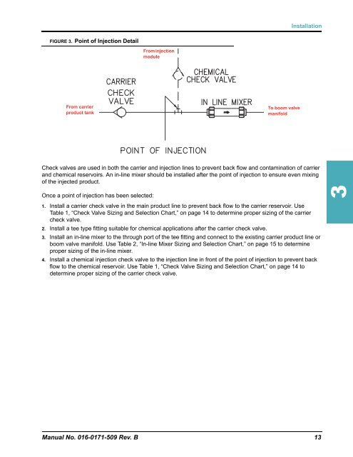
FIGURE 3. Point of Injection Detail<br />
From carrier<br />
product tank<br />
<strong>Installation</strong><br />
Check valves are used in both the carrier and injection lines to prevent back flow and contamination of carrier<br />
and chemical reservoirs. An in-line mixer should be installed after the point of injection to ensure even mixing<br />
of the injected product.<br />
Once a point of injection has been selected:<br />
From injection<br />
module<br />
To boom valve<br />
manifold<br />
1. Install a carrier check valve in the main product line to prevent back flow to the carrier reservoir. Use<br />
Table 1, “Check Valve Sizing and Selection Chart,” on page 14 to determine proper sizing of the carrier<br />
check valve.<br />
2. Install a tee type fitting suitable for chemical applications after the carrier check valve.<br />
3. Install an in-line mixer to the through port of the tee fitting and connect to the existing carrier product line or<br />
boom valve manifold. Use Table 2, “In-line Mixer Sizing and Selection Chart,” on page 15 to determine<br />
proper sizing of the in-line mixer.<br />
4. Install a chemical injection check valve to the injection line in front of the point of injection to prevent back<br />
flow to the chemical reservoir. Use Table 1, “Check Valve Sizing and Selection Chart,” on page 14 to<br />
determine proper sizing of the carrier check valve.<br />
<strong>Manual</strong> No. 016-0171-509 Rev. B 13<br />
3