- Page 1 and 2:
Specification of Reactive Hardware/
- Page 3:
to Leny, Inge and our parents
- Page 7 and 8:
Contents Acknowledgements v 1 Intro
- Page 9 and 10:
CONTENTS ix 4.6.5 Aggregate Semanti
- Page 11 and 12:
CONTENTS xi 6 Modelling of Concurre
- Page 13 and 14:
CONTENTS xiii 6.6.7.2 System Specif
- Page 15 and 16:
CONTENTS xv 11.4.2.3 Requirements C
- Page 17 and 18:
List of Figures 1.1 Chapter Overvie
- Page 19 and 20:
LIST OF FIGURES xix 6.16 Strongly D
- Page 21 and 22:
Chapter 1 Introduction 1.1 Objectiv
- Page 23 and 24:
1.1 Objectives 3 understood and sti
- Page 25 and 26:
1.1 Objectives 5 Informal and Forma
- Page 27 and 28:
1.2 Thesis Organisation 7 Chapter 1
- Page 29 and 30:
1.2 Thesis Organisation 9 Recommend
- Page 31 and 32:
Chapter 2 On Specification of React
- Page 33 and 34:
2.3 Specifications, Models and View
- Page 35 and 36:
2.3 Specifications, Models and View
- Page 37 and 38:
2.3 Specifications, Models and View
- Page 39 and 40:
2.4 Specification Languages, Formal
- Page 41 and 42:
2.4 Specification Languages, Formal
- Page 43 and 44: 2.5 Modelling Concepts 23 entirety.
- Page 45 and 46: 2.5 Modelling Concepts 25 Tradition
- Page 47 and 48: 2.6 Activity Frameworks for Specifi
- Page 49 and 50: 2.6 Activity Frameworks for Specifi
- Page 51 and 52: 2.7 Summary 31 offer many guideline
- Page 53 and 54: Chapter 3 Concepts for Analysis, Sp
- Page 55 and 56: 3.3 Concepts 35 3. creation of a sy
- Page 57 and 58: 3.5 Combining Compatible Concepts 3
- Page 59 and 60: 3.6 Practical Use of Concepts 39 3.
- Page 61 and 62: 3.6 Practical Use of Concepts 41 Th
- Page 63 and 64: 3.6 Practical Use of Concepts 43 ac
- Page 65 and 66: 3.6 Practical Use of Concepts 45 ac
- Page 67 and 68: 3.6 Practical Use of Concepts 47 wa
- Page 69 and 70: 3.6 Practical Use of Concepts 49 Ge
- Page 71 and 72: 3.6 Practical Use of Concepts 51 Re
- Page 73 and 74: 3.7 Summary and Concluding Remarks
- Page 75 and 76: Chapter 4 Abstraction of a Problem
- Page 77 and 78: 4.1 Introduction 57 earlier phase t
- Page 79 and 80: 4.2 Objects 59 An object can mean t
- Page 81 and 82: 4.2 Objects 61 wonder what other ob
- Page 83 and 84: 4.3 Classes 63 A message interface
- Page 85 and 86: 4.3 Classes 65 Class B Attributes M
- Page 87 and 88: 4.4 Data Objects and Process Object
- Page 89 and 90: 4.4 Data Objects and Process Object
- Page 91 and 92: 4.4 Data Objects and Process Object
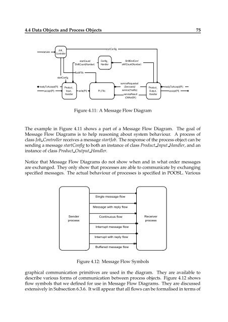
- Page 93: 4.4 Data Objects and Process Object
- Page 97 and 98: 4.4 Data Objects and Process Object
- Page 99 and 100: 4.5 Clusters 79 flows. Clusters ena
- Page 101 and 102: 4.6 Aggregates 81 Therefore a compl
- Page 103 and 104: 4.6 Aggregates 83 4.6.4 Clustered A
- Page 105 and 106: 4.6 Aggregates 85 An old philosophi
- Page 107 and 108: 4.7 Identity and Object Identifiers
- Page 109 and 110: 4.8 Properties of Composites 89 for
- Page 111 and 112: 4.8 Properties of Composites 91 com
- Page 113 and 114: 4.8 Properties of Composites 93 Whe
- Page 115 and 116: 4.8 Properties of Composites 95 In
- Page 117 and 118: 4.9 Channel Hiding 97 Servant A Sup
- Page 119 and 120: 4.11 Composites and Hierarchies 99
- Page 121 and 122: 4.12 Object Variety 101 Part class
- Page 123 and 124: 4.13 Object Class Models 103 Anothe
- Page 125 and 126: 4.13 Object Class Models 105 of obj
- Page 127 and 128: 4.14 Attributes and Variables 107 c
- Page 129 and 130: 4.14 Attributes and Variables 109 4
- Page 131 and 132: 4.15 Operations, Services, Methods
- Page 133 and 134: 4.15 Operations, Services, Methods
- Page 135 and 136: 4.17 Summary 115 Accidental Propert
- Page 137 and 138: Chapter 5 Concepts for the Integrat
- Page 139 and 140: 5.2 Architecture 119 Requirements D
- Page 141 and 142: 5.3 Design Philosophy 121 this. The
- Page 143 and 144: 5.4 Essential Model and Extended Mo
- Page 145 and 146:
5.4 Essential Model and Extended Mo
- Page 147 and 148:
5.6 Architecture and Implementation
- Page 149 and 150:
5.7 Views 129 Management £ £ £ P
- Page 151 and 152:
5.7 Views 131 Behaviour Behaviour U
- Page 153 and 154:
5.8 Boundaries 133 5.8 Boundaries 5
- Page 155 and 156:
5.8 Boundaries 135 x x Object A y z
- Page 157 and 158:
5.8 Boundaries 137 x w w x Object A
- Page 159 and 160:
5.8 Boundaries 139 In Chapter 10 we
- Page 161 and 162:
5.9 Transformations 141 The modific
- Page 163 and 164:
5.10 Formalisation 143 Level 1 Leve
- Page 165 and 166:
5.11 Summary 145 Behaviour Requirem
- Page 167 and 168:
Chapter 6 Modelling of Concurrent R
- Page 169 and 170:
6.2 Concurrency and Synchronisation
- Page 171 and 172:
6.2 Concurrency and Synchronisation
- Page 173 and 174:
6.2 Concurrency and Synchronisation
- Page 175 and 176:
6.2 Concurrency and Synchronisation
- Page 177 and 178:
6.3 Communication 157 between proce
- Page 179 and 180:
6.3 Communication 159 or to transfo
- Page 181 and 182:
6.3 Communication 161 6.3.3.4 Messa
- Page 183 and 184:
6.3 Communication 163 Synchronous m
- Page 185 and 186:
6.3 Communication 165 channel-name
- Page 187 and 188:
6.3 Communication 167 can be descri
- Page 189 and 190:
6.3 Communication 169 statement aft
- Page 191 and 192:
6.3 Communication 171 (normalCourse
- Page 193 and 194:
6.3 Communication 173 ∞ client re
- Page 195 and 196:
6.3 Communication 175 There is a gr
- Page 197 and 198:
6.3 Communication 177 process A pro
- Page 199 and 200:
6.3 Communication 179 Clocks An int
- Page 201 and 202:
6.3 Communication 181 whether the s
- Page 203 and 204:
6.3 Communication 183 6.3.9.4 Model
- Page 205 and 206:
6.3 Communication 185 6.3.10.2 Desc
- Page 207 and 208:
6.4 Distribution 187 force to take
- Page 209 and 210:
6.4 Distribution 189 is that the in
- Page 211 and 212:
6.4 Distribution 191 links to each
- Page 213 and 214:
6.4 Distribution 193 6.4.6 Distribu
- Page 215 and 216:
6.5 Scenarios 195 entities. This su
- Page 217 and 218:
6.5 Scenarios 197 startJob readyToA
- Page 219 and 220:
6.5 Scenarios 199 collection of tex
- Page 221 and 222:
6.6 Dynamic Behaviour 201 selection
- Page 223 and 224:
6.6 Dynamic Behaviour 203 processes
- Page 225 and 226:
6.6 Dynamic Behaviour 205 even for
- Page 227 and 228:
6.6 Dynamic Behaviour 207 with the
- Page 229 and 230:
6.6 Dynamic Behaviour 209 6.6.4 Sep
- Page 231 and 232:
6.6 Dynamic Behaviour 211 6.6.5 Mod
- Page 233 and 234:
6.6 Dynamic Behaviour 213 to pay at
- Page 235 and 236:
6.6 Dynamic Behaviour 215 A method
- Page 237 and 238:
6.6 Dynamic Behaviour 217 to happen
- Page 239 and 240:
6.6 Dynamic Behaviour 219 c a Multi
- Page 241 and 242:
6.6 Dynamic Behaviour 221 but not t
- Page 243 and 244:
6.7 Real-Time Modelling 223 claimed
- Page 245 and 246:
6.7 Real-Time Modelling 225 in the
- Page 247 and 248:
6.8 Summary 227 They can graphicall
- Page 249 and 250:
Chapter 7 Introduction to the Seman
- Page 251 and 252:
7.2 A Brief Language Characterisati
- Page 253 and 254:
7.3 The Role of Semantics 233 7.3 T
- Page 255 and 256:
7.4 Mathematical Preliminaries 235
- Page 257 and 258:
7.4 Mathematical Preliminaries 237
- Page 259 and 260:
7.5 Concluding Remarks 239 0 ¡ Bin
- Page 261 and 262:
Chapter 8 Data Part of POOSL Chapte
- Page 263 and 264:
8.3 Formal Syntax 243 runk, and cun
- Page 265 and 266:
8.4 Context Conditions 245 Further,
- Page 267 and 268:
8.5 A Computational Semantics 247 T
- Page 269 and 270:
8.5 A Computational Semantics 249 w
- Page 271 and 272:
8.5 A Computational Semantics 251 s
- Page 273 and 274:
8.6 Primitive deepCopy Messages 253
- Page 275 and 276:
8.6 Primitive deepCopy Messages 255
- Page 277 and 278:
8.7 Example: Complex Numbers 257 is
- Page 279 and 280:
8.8 Summary and Concluding Remarks
- Page 281 and 282:
Chapter 9 Process Part of POOSL Cha
- Page 283 and 284:
9.3 Formal Syntax 263 In almost any
- Page 285 and 286:
9.3 Formal Syntax 265 The fourth st
- Page 287 and 288:
9.3 Formal Syntax 267 call of the f
- Page 289 and 290:
9.4 Context Conditions 269 We are n
- Page 291 and 292:
9.5 A Computational Interleaving Se
- Page 293 and 294:
9.5 A Computational Interleaving Se
- Page 295 and 296:
9.5 A Computational Interleaving Se
- Page 297 and 298:
9.5 A Computational Interleaving Se
- Page 299 and 300:
9.5 A Computational Interleaving Se
- Page 301 and 302:
9.5 A Computational Interleaving Se
- Page 303 and 304:
9.5 A Computational Interleaving Se
- Page 305 and 306:
9.6 Example: A Simple Handshake Pro
- Page 307 and 308:
9.6 Example: A Simple Handshake Pro
- Page 309 and 310:
9.6 Example: A Simple Handshake Pro
- Page 311 and 312:
9.7 The Development of POOSL 291 is
- Page 313 and 314:
9.7 The Development of POOSL 293 da
- Page 315 and 316:
9.7 The Development of POOSL 295 e
- Page 317 and 318:
9.7 The Development of POOSL 297 Em
- Page 319 and 320:
9.7 The Development of POOSL 299 (o
- Page 321 and 322:
9.8 Summary 301 To prepare the deve
- Page 323 and 324:
Chapter 10 Behaviour-Preserving Tra
- Page 325 and 326:
10.2 Instance Structure Diagrams 30
- Page 327 and 328:
10.2 Instance Structure Diagrams 30
- Page 329 and 330:
10.3 Some Properties of Transformat
- Page 331 and 332:
10.4 A System of Basic Transformati
- Page 333 and 334:
10.4 A System of Basic Transformati
- Page 335 and 336:
10.4 A System of Basic Transformati
- Page 337 and 338:
10.4 A System of Basic Transformati
- Page 339 and 340:
10.5 Example: The Elevator Problem
- Page 341 and 342:
10.5 Example: The Elevator Problem
- Page 343 and 344:
10.5 Example: The Elevator Problem
- Page 345 and 346:
10.5 Example: The Elevator Problem
- Page 347 and 348:
10.7 On the Fundamental Limitations
- Page 349 and 350:
10.7 On the Fundamental Limitations
- Page 351 and 352:
10.8 Summary 331 are transformation
- Page 353 and 354:
Chapter 11 SHE Framework Chapter 1
- Page 355 and 356:
11.2 SHE Context and Phases 335 Inf
- Page 357 and 358:
11.2 SHE Context and Phases 337 a p
- Page 359 and 360:
11.2 SHE Context and Phases 339 11.
- Page 361 and 362:
11.3 SHE Framework 341 the system.
- Page 363 and 364:
11.4 Essential Specification Modell
- Page 365 and 366:
11.4 Essential Specification Modell
- Page 367 and 368:
11.4 Essential Specification Modell
- Page 369 and 370:
11.4 Essential Specification Modell
- Page 371 and 372:
11.4 Essential Specification Modell
- Page 373 and 374:
11.4 Essential Specification Modell
- Page 375 and 376:
11.4 Essential Specification Modell
- Page 377 and 378:
11.4 Essential Specification Modell
- Page 379 and 380:
11.4 Essential Specification Modell
- Page 381 and 382:
11.4 Essential Specification Modell
- Page 383 and 384:
11.4 Essential Specification Modell
- Page 385 and 386:
11.4 Essential Specification Modell
- Page 387 and 388:
11.5 Extended Specification Modelli
- Page 389 and 390:
11.5 Extended Specification Modelli
- Page 391 and 392:
11.5 Extended Specification Modelli
- Page 393 and 394:
11.5 Extended Specification Modelli
- Page 395 and 396:
Chapter 12 Case Study Chapter 1 Cha
- Page 397 and 398:
12.2 Initial Requirements Descripti
- Page 399 and 400:
12.3 The Essential Specification 37
- Page 401 and 402:
12.3 The Essential Specification 38
- Page 403 and 404:
12.3 The Essential Specification 38
- Page 405 and 406:
12.3 The Essential Specification 38
- Page 407 and 408:
12.3 The Essential Specification 38
- Page 409 and 410:
12.3 The Essential Specification 38
- Page 411 and 412:
12.3 The Essential Specification 39
- Page 413 and 414:
12.3 The Essential Specification 39
- Page 415 and 416:
12.3 The Essential Specification 39
- Page 417 and 418:
12.4 Towards an Extended Specificat
- Page 419 and 420:
12.5 Concluding Remarks 399 i1 DIST
- Page 421 and 422:
12.5 Concluding Remarks 401 Feeder
- Page 423 and 424:
Chapter 13 Conclusions and Future W
- Page 425 and 426:
13.2 P.H.A. van der Putten’s Cont
- Page 427 and 428:
13.2 P.H.A. van der Putten’s Cont
- Page 429 and 430:
13.4 Related Results 409 The notion
- Page 431 and 432:
Appendix A The POOSL Transition Sys
- Page 433 and 434:
A.1 The Data Part of POOSL 413 (12)
- Page 435 and 436:
A.2 The Process Part of POOSL 415 A
- Page 437 and 438:
A.2 The Process Part of POOSL 417 (
- Page 439 and 440:
A.2 The Process Part of POOSL 419 (
- Page 441 and 442:
A.2 The Process Part of POOSL 421 i
- Page 443 and 444:
Appendix B Proofs of Propositions a
- Page 445 and 446:
Proofs of Propositions and Transfor
- Page 447 and 448:
Proofs of Propositions and Transfor
- Page 449 and 450:
Proofs of Propositions and Transfor
- Page 451 and 452:
Proofs of Propositions and Transfor
- Page 453 and 454:
Proofs of Propositions and Transfor
- Page 455 and 456:
Appendix C Glossary of Symbols This
- Page 457 and 458:
Glossary of Symbols 437 267 Cp ¥¡
- Page 459 and 460:
References [AB90] P. America and F.
- Page 461 and 462:
REFERENCES 441 [C [C [C 86] B. Cohe
- Page 463 and 464:
REFERENCES 443 [Her90] A.J.H. Herbe
- Page 465 and 466:
REFERENCES 445 [MV93] S. Mauw and G
- Page 467 and 468:
REFERENCES 447 [vE89] P. van Eijk.
- Page 469 and 470:
Index abort, 297 abstract action so
- Page 471 and 472:
INDEX 451 strong, 190, 293 subsyste
- Page 473 and 474:
INDEX 453 delay, 178 do-statement,
- Page 475 and 476:
Summary This combined thesis descri
- Page 477 and 478:
Samenvatting Dit gecombineerde proe
- Page 479:
Curricula Vitae Piet van der Putten


