This environmental impact assessment for Kriegers flak ... - Vattenfall
This environmental impact assessment for Kriegers flak ... - Vattenfall
This environmental impact assessment for Kriegers flak ... - Vattenfall

Create successful ePaper yourself
Turn your PDF publications into a flip-book with our unique Google optimized e-Paper software.
26 DESCRIPTION OF THE WIND FARM<br />
Denmark but it also stretches into the German and the<br />
Swedish EEZ.<br />
The designated area <strong>for</strong> the wind farm lies outside of<br />
Swedish territorial waters but inside the EEZ where it<br />
borders to the German and Danish EEZ.<br />
The nearest landmass in Sweden is Trelleborg<br />
(about 30 km), in Denmark Mön (about 34 km) and in<br />
Germany Rügen (about 40 km).<br />
The total area of the wind farm will maximum be 6<br />
km x 12.5 km. The coordinates and the corresponding<br />
reference points are described in appendix 2.1.<br />
5.3. Placing of the turbines<br />
The distance between the turbines will be determined<br />
during the detailed development work. Several different<br />
conÞ gurations have been discussed and the relevant<br />
distances between the turbines in a row/distances<br />
between rows, were at that time 575/900 metres and<br />
800/900 metres respectively.<br />
The turbines should, generally speaking, be erected<br />
where the lowest water depth is present on the site, as<br />
this is a condition <strong>for</strong> a cost effective placement of the<br />
turbines. The Þ nal micrositing will have to consider the<br />
so-called wind-shadow. The turbines should, there<strong>for</strong>e,<br />
not be placed too close as they would otherwise steal<br />
wind from each other.<br />
During the micrositing process, emphasis will also<br />
be on a conÞ guration that will result in the lowest possible<br />
<strong>impact</strong> on the salt water seabed-current.<br />
5.4. Layout<br />
5.4.1 The wind Turbines<br />
A wind turbine consists of a rotor, a nacelle and a<br />
tower.<br />
The rotor has three blades of about 65 metres length<br />
each, which are mounted on a hub. When the wind<br />
passes the rotor, the kinetic energy of the air is converted<br />
to a torque along the main shaft. The electricity<br />
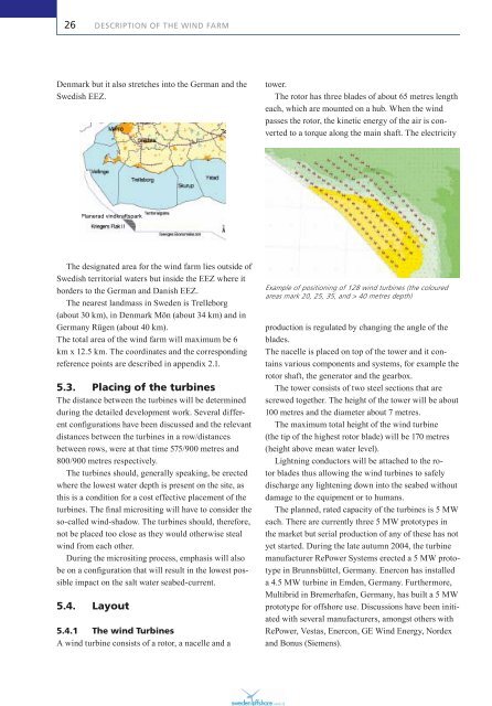
Example of positioning of 128 wind turbines (the coloured<br />
areas mark 20, 25, 35, and > 40 metres depth)<br />
production is regulated by changing the angle of the<br />
blades.<br />
The nacelle is placed on top of the tower and it contains<br />
various components and systems, <strong>for</strong> example the<br />
rotor shaft, the generator and the gearbox.<br />
The tower consists of two steel sections that are<br />
screwed together. The height of the tower will be about<br />
100 metres and the diameter about 7 metres.<br />
The maximum total height of the wind turbine<br />
(the tip of the highest rotor blade) will be 170 metres<br />
(height above mean water level).<br />
Lightning conductors will be attached to the rotor<br />
blades thus allowing the wind turbines to safely<br />
discharge any lightening down into the seabed without<br />
damage to the equipment or to humans.<br />
The planned, rated capacity of the turbines is 5 MW<br />
each. There are currently three 5 MW prototypes in<br />
the market but serial production of any of these has not<br />
yet started. During the late autumn 2004, the turbine<br />
manufacturer RePower Systems erected a 5 MW prototype<br />
in Brunnsbüttel, Germany. Enercon has installed<br />
a 4.5 MW turbine in Emden, Germany. Furthermore,<br />
Multibrid in Bremerhafen, Germany, has built a 5 MW<br />
prototype <strong>for</strong> offshore use. Discussions have been initiated<br />
with several manufacturers, amongst others with<br />
RePower, Vestas, Enercon, GE Wind Energy, Nordex<br />
and Bonus (Siemens).