

TELE-TECH & - AmericanRadioHistory.Com
TELE-TECH & - AmericanRadioHistory.Com
TELE-TECH & - AmericanRadioHistory.Com

You also want an ePaper? Increase the reach of your titles
YUMPU automatically turns print PDFs into web optimized ePapers that Google loves.
fin<br />
Air Cooling A<br />
By DR. M. MARK<br />
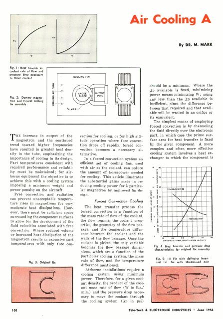
Fig. 1: Heat transfer vs.<br />
coolant rate of flow and<br />
pressure drop necessary<br />
to move coolant<br />
Fig. 2: Dummy magnetron<br />
and typical cooling<br />
fin assembly<br />
a<br />
ccá<br />
_ --<br />
ó<br />
o--<br />
COOLING FIN<br />
is,MAX-/<br />
THE increase in output of the<br />
magnetron and the continued<br />
trend toward higher frequencies<br />
have resulted in greater heat density<br />
in the tube, emphasizing the<br />
importance of cooling in its design.<br />
Part temperatures consistent with<br />
required performance and reliability<br />
must be maintained; for airborne<br />
equipment the objective is to<br />
achieve this with a cooling system<br />
imposing a minimum weight and<br />
power penalty on the aircraft.<br />
Free convection and radiation<br />
can prevent unacceptable temperature<br />
rises in magnetrons for very<br />
moderate heat dissipations. However,<br />
there must be sufficient space<br />
surrounding the component surfaces<br />
to allow for the development of the<br />
fluid velocities associated with free<br />
convection. Where reduced volume<br />
or increased heat dissipation of the<br />
magnetron results in excessive part<br />
temperatures with only free con-<br />
Fig. 3: Original fin<br />
ANODE<br />
BLOCK<br />
X<br />
OUTPUT<br />
PIPE<br />
IBN<br />
vection for cooling, or for high altitude<br />
operation where free convection<br />
drops off rapidly, forced convection<br />
becomes a necessary alternative.<br />
In a forced convection system an<br />
efficient set of cooling fins, used<br />
with air as the coolant, can reduce<br />
the amount of horsepower needed<br />
for cooling. This article illustrates<br />
the substantial gains made in reducing<br />
cooling power for á particular<br />
magnetron by improved fin design.<br />
Forced Convection Cooling<br />
The heat transfer process for<br />
forced convection is a function of<br />
the mass rate of flow of the coolant,<br />
the flow regime, the coolant properties,<br />
the geometry of the flow passage,<br />
and the temperature difference<br />
between the coolant and the<br />
walls of the flow passage. Once the<br />
coolant is picked, the only variable<br />
becomes the flow passage dimensions,<br />
which are a function of the<br />
particular cooling system, the mass<br />
rate of flow, and the temperature<br />
difference mentioned.<br />
Airborne installations require a<br />
cooling system using minimum<br />
power. Therefore, for a given coolant<br />
density, the product of the coolant<br />
mass rate of flow (W in lbs./<br />
min.) and the pressure drop necessary<br />
to move the coolant through<br />
the cooling system (.p in psi)<br />
should be a minimum. Where the<br />
Ap available is fixed, minimizing<br />
power means minimizing W; using<br />
any less than the :gyp available is<br />
inefficient, since the difference between<br />
that required and that available<br />
will be wasted in an orifice or<br />
its equivalent.<br />
The simplest means of employing<br />
forced convection is by channeling<br />
the fluid directly over the electronic<br />
part, in which case the prime surface<br />
area for heat transfer is fixed<br />
by the given component. A more<br />
complex and often more effective<br />
cooling system involves a heat exchanger<br />
to which the component is<br />
I6 60<br />
14 !, 70<br />
a<br />
12 i60<br />
3<br />
10 i 50<br />
4 s 0<br />
6 u 30<br />
4 = 20<br />
TEMP ERATURE RISE<br />
PRESSURE DROP<br />
2 10 _<br />
10 20 30 40 50 60<br />
AIR n061,CU.FT/MI11, DEMSITT0T226<br />
6/CU. FT.<br />
Fig. 4: Heat transfer and pressure drop<br />
characteristics for original fin assembly<br />
Fig. 5: II) Fin with deflector insert<br />
and I 1 with streamlined exit<br />
100<br />
Tele -Tech & ELECTRONIC INDUSTRIES June 1956


