

TELE-TECH & - AmericanRadioHistory.Com
TELE-TECH & - AmericanRadioHistory.Com
TELE-TECH & - AmericanRadioHistory.Com

You also want an ePaper? Increase the reach of your titles
YUMPU automatically turns print PDFs into web optimized ePapers that Google loves.
9<br />
Antenna Arrays<br />
(Continued from page 205)<br />
magnitude evaluation is then made<br />
and the array efficiency in field<br />
strength computed and assigned as<br />
previously.<br />
Examples<br />
(a) An array of two 60 radiators<br />
spaced at 90 °. I;, = 1.0 /0 and I,,<br />
0.9 / -150. The pattern shape is derived<br />
from the above, and the RMS<br />
value in reference units is 1.033.<br />
From an impedance analysis it is<br />
found that L, 8.31 a. and I,,<br />
7.48 a., assuming a total power of<br />
1 kw. Hence 1.033 is equivalent to<br />
8.60 a.<br />
A 60° radiator alone radiates 181<br />
my -'m at one mile, has a base impedance<br />
of 14 -- j 76, and thus a<br />
base current of 8.45 a. for 1 kw.<br />
Therefore the array RMs in field<br />
strength is (8.60/8.45) x 181 = 184<br />
my /m at one mile. See Fig. 1.<br />
(b) An array of two 60° radiators<br />
spaced at 210 °. I = 1.0 /0 and I -<br />
0.9 / -10. The pattern shape is derived<br />
and the RMS value in reference<br />
units is 1.055.<br />
From an impedance analysis it is<br />
found that Ie = 7.21 a. and Il, _<br />
6.49 a., assuming a power input to<br />
the array of 1 kw. Hence 1.055 is<br />
equivalent to 7.60 a.<br />
As previously, the array RDAs in<br />
field strength is (7.60/8.45) x 181 =<br />
163 my /m at one mile. See Fig. 2.<br />
(c) An array of two radiators A<br />
= 90° and B = 60° and spaced at<br />
210 °.I, = 1.0 LI and II, =0.9 / -10.<br />
The pattern shape is derived and<br />
the RMS value in reference units is<br />
1.055.<br />
From an impedance analysis it is<br />
found that I, = 3.54 a. and II, = 6.61<br />
a., assuming a power input to the<br />
array of 1 kw. It is also found that<br />
P° = 515 w. and P,, = 485 w. Since<br />
A is 90° with an omni field of 190<br />
my /m and B is 60° with an omni<br />
field of 181 my /m, then Ea = 136<br />
my /m for 515 w. and E1, = 126 my /m<br />
for 485 w. The Rss for Ea and El,<br />
combined is 185.5 my /m. This value<br />
is equivalent to a 75° radiator with<br />
a base impedance of 27.5 + j0 and a<br />
base current of 6.03 a. for omni<br />
operation.<br />
Assume then that the array is of<br />
two equivalent radiators 75° in<br />
height and spaced at 210 °. The parameters<br />
are as above and the RMS<br />
value is 1.055.<br />
From an impedance analysis (75°<br />
radiators) it is found that L, = 5.17<br />
(Continued on page 208)<br />
lì<br />
Quality- Minded Engineers<br />
Specify<br />
CONRAC MONITORS<br />
Conrac Monitors are designed for continuous, trouble -free<br />
service. Engineered to prevent costly repair bills, down time<br />
and to save valuable man hours, Conrac Monitors are found<br />
wherever exact monitoring is needed. You'll see them in use at<br />
all of the major networks and a majority of stations.<br />
Color Monitor CH 21 is a self -<br />
contained picture monitor that can be operated<br />
from NTSC encoded color video signals or<br />
from simultaneous red, green and blue video<br />
signals. It employs a three -gun tri -color picture<br />
tube -type 2IAXP22. All operating and set up<br />
controls, as well as o test po.nt for Y, 1, Q,<br />
R, G and B, ore accessible from the front.<br />
Schematic, engineering doto and specifications<br />
fui nished on request.<br />
Monochrome Monitors- Conrac manufac-<br />
tures three monochrome monitors: the CB 17 -A,<br />
a professional monitor of the highest quality<br />
and the CF and CG Series general purpose<br />
mon tors.<br />
The CB 17 -A, designed for control room and<br />
on -stage use, employs a 17" aluminized rectangular<br />
picture tube. It may be rack mounted<br />
in o standard 19" relay rack (No. CB 17A /R),<br />
or furnished in utility heavy gauge steel cabinet<br />
with carrying handles (No. CB I7A /C).<br />
The CF and CG Series of video monitors are<br />
general purpose monitors intended for broadcast<br />
or industrial use. They present bright,<br />
high definition pictures in continuous operation<br />
with a minimum of maintenance.<br />
The CF Series uses a 70° deflection system for<br />
both 17" and 21" kinescopes. The CG Series<br />
has a 90° deflection system for 24" and 27"<br />
kinescopes. All chassis are supplied with picture<br />
tube. The CF 17 is available for 19"<br />
relay rock mounting, in a utility cabinet or<br />
os a chassis. Model numbers ore os follows:<br />
CF 17 -N CF chassis with 17" picture tube.<br />
CF 17 -R CF chassis with 17" picture tube in<br />
mounting for standard 19" relay rack.<br />
CF 17 -C CF chassis with 17" picture tube in<br />
steel housing equipped with carrying handles.<br />
CF 21 -N CF chassis with 21" picture tube.<br />
CF 21 -C CF chassis with 21" picture tube in<br />
steel housing equipped with carrying handles.<br />
CG 24 -N CG chassis with 24" picture tube.<br />
CG 27 -N CG chassis with 27" picture tube.<br />
Schematics, engineering dota and specifications<br />
available upon request.<br />
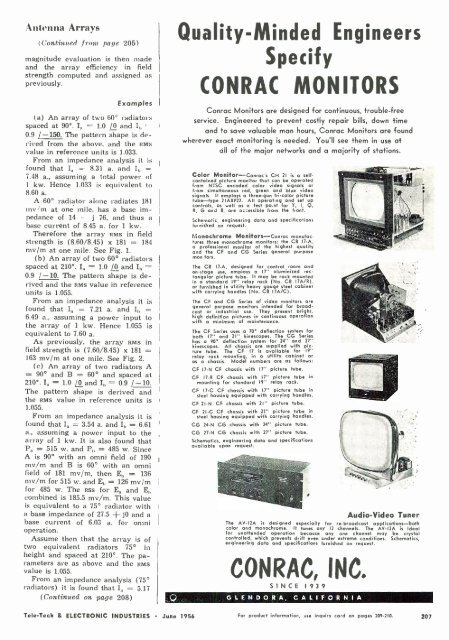
Audio -Video Tuner<br />
The AV -12A is designed especially for re- broadcast applications -both<br />
color and monochrome. It tunes any 12 channels. The AV -12A is ideal<br />
for unattended operation because any one channel may be crystal<br />
controlled, which prevents drift even under extreme conditions. Schematics,<br />
engineering data and specifications furnished on request.<br />
CONRAC, INC<br />
S I N C E 1<br />
3 9<br />
GLENDORA, CALIFORNIA<br />
Tele -Tech & ELECTRONIC INDUSTRIES June 1956 For product information, use inquiry cord on pages 209 -210. 207


