

TELE-TECH & - AmericanRadioHistory.Com
TELE-TECH & - AmericanRadioHistory.Com
TELE-TECH & - AmericanRadioHistory.Com

You also want an ePaper? Increase the reach of your titles
YUMPU automatically turns print PDFs into web optimized ePapers that Google loves.
Regulation in less than '/so th cycle<br />
ASDE Radar<br />
(Continued from page 185)<br />
fi:lt:l1.ldi:l.a1 :11u IlElliif''i.<br />
:IIi41i 111;?l :@iL:Plll! 1111 1:1'111'IN`i':ppI<br />
-1i:(_:;iiïi'!t!.'ll'l'sl`Li''i1i1' 'Ii'I<br />
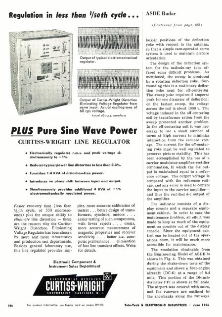
Output of typical electromechanical<br />
regulator.<br />
;.=7--; r17g.<br />
'Imill:<br />
1<br />
Output of Curtiss -Wright Distortion<br />
Eliminating Voltage Regulator from<br />
same input. Actual oscillograms of<br />
60 cps voltage.<br />
Actual 60 c.p.s. waveform<br />
PLUS Pure Sine Wave Power<br />
CURTISS -WRIGHT LINE REGULATOR<br />
Electronically regulates r.m.s. and peak voltage simultaneously<br />
to 1°0.<br />
Reduces typical power line distortion to less than 0.39%.<br />
Furnishes 1.4 KVA of distortion -free power.<br />
Introduces no phase shift between input and output.<br />
Simultaneously provides additional 4 KVA of =.1<br />
electromechanically regulated power.<br />
Faster recovery time (less than<br />
1 /50th cycle, or 330 microseconds)<br />
plus the unique ability to<br />
eliminate line distortion - these<br />
are the reasons why the Curtiss -<br />
Wright Distortion Eliminating<br />
Voltage Regulator has been chosen<br />
by more and more laboratories<br />
and production test departments.<br />
Besides general laboratory use,<br />
this line regulator provides sim-<br />
Electronic <strong>Com</strong>ponent &<br />
Instrument Sales Department<br />
ELECTRONICS<br />
pier, more accurate calibration of<br />
meters ... better design of transformers,<br />
synchros, motors . . .<br />
easier testing of such components,<br />
with fewer rejects . . . easier,<br />
more accurate measurement of<br />
magnetic properties and receiver<br />
sensitivity . . . better a.c. computer<br />
performance ... elimination<br />
of fast line transient effects. Write<br />
for details.<br />
DIVISION<br />
CURTISS»WRIGHT<br />
CORPORATION CARLSTADT, N. J.<br />
lock -in positions of the deflection<br />
yoke with respect to the antenna,<br />
so that a simple cam -operated servo<br />
system is used to maintain picture<br />
orientation.<br />
The design of the deflection system<br />
for the cathode -ray tube offered<br />
some difficult problems. As<br />
mentioned, the sweep is produced<br />
by a rotating deflection yoke. Surrounding<br />
this is a stationary deflection<br />
yoke used for off -centering.<br />
The sweep yoke requires 2 amperes<br />
peak for one diameter of deflection;<br />
on the fastest sweep, the voltage<br />
across the coil is about 1000 v. The<br />
voltage induced in the off -centering<br />
coil by transformer action from the<br />
sweep presented another problem.<br />
In the off -centering coil it was necessary<br />
to use a small number of<br />
turns at high current to minimize<br />
interaction from the induced voltage.<br />
The current for the off- centering<br />
yoke must be well regulated to<br />
preserve picture stability. This has<br />
been accomplished by the use of a<br />
carrier modulator -amplifier- rectifier<br />
combination, in which the d-c output<br />
is maintained equal to a reference<br />
voltage. The output voltage is<br />
compared with the reference voltage,<br />
and any error is used to control<br />
the input to the carrier amplifier -<br />
and thus the rectified d-c output of<br />
the amplifier.<br />
The indicator consists of a display<br />
console and a separate equipment<br />
cabinet. In order to ease the<br />
maintenance problem, an effort was<br />
made to keep as much of the equipment<br />
as possible out of the display<br />
console. Since the equipment cabinet<br />
can be located out of the operations<br />
room, it will be much more<br />
accessible for maintenance.<br />
The resolution obtainable from<br />
the Engineering Model of ASDE is<br />
shown in Fig. 4. This was obtained<br />
during the shake -down tests of the<br />
equipment and shows a four -engine<br />
aircraft (DC -6) at a range of 0.4<br />
mile. This portion of the 16 -inchdiameter<br />
PPI is shown at full scale.<br />
The airport was covered with snow,<br />
and the runways are outlined by<br />
the snowbanks along the runways.<br />
186<br />
For product information, use inquiry card on pages 209 -210<br />
Tele -Tech & ELECTRONIC INDUSTRIES June 1956


