

TELE-TECH & - AmericanRadioHistory.Com
TELE-TECH & - AmericanRadioHistory.Com
TELE-TECH & - AmericanRadioHistory.Com

You also want an ePaper? Increase the reach of your titles
YUMPU automatically turns print PDFs into web optimized ePapers that Google loves.
FREED<br />
OFFERS FOR IMMEDIATE<br />
DELIVERY FROM STOCK<br />
MIL -T -27 STANDARD<br />
POWER, FILAMENT, PULSE<br />
\s and AUDIO TRANSFORMERS<br />
POWER TRANSFORMERS<br />
Filament Filament<br />
#1 #2<br />
Hi .. - ., .4 MIL<br />
Cat. Volt c = 2,É É - E Case<br />
No. Sec. et . e s as Size<br />
400/200 V 185 .070 6.3/5 2 6.3 3 H11<br />
4 Jr<br />
2<br />
MGP1<br />
MGP2 650 V 260 .070 6.3/5 6.3<br />
MGP3 650 V 245 .150 6.3 5 5.0 3 KB<br />
MGP4 800 V 318 .175 5.0 3 6.3 B LB<br />
MGM 900 V 345 .250 5.0 3 6.3 e MB<br />
MOPE 700 V 255 .250 KB<br />
MGP7 1100 V 419 .250 LB<br />
MGPB 1600 V 640 .250 NB<br />
FILAMENT TRANSFORMERS<br />
Cat. Secondary Test MIL<br />
No. Volt Amp VRMS Case<br />
MGF1 2.5 3.0 2,500 EB<br />
MGF2 2.5 10.0 2,500 GB<br />
MGF3 5.0 3.0 2,500 FB<br />
MGF4 5.0 10.0 2,500 HB<br />
MGF5 6.3 2.0 ' 2,500 FB<br />
MGF6 6.3 5.0 2,500 GB<br />
MGF7 6.3 10.0 2,500 JB<br />
MGF8 6.3 20.0 2,500 KB<br />
MGF9 2.5 10.0 10,000 JB<br />
MGFIO 5.0 10.0 10,000 KB<br />
ug<br />
e_<br />
s:O<br />
PULSE<br />
Pulsa<br />
Voltage<br />
Kilovolts<br />
TRANSFORMERS<br />
- E.<br />
eM '<br />
2<br />
e<br />
M<br />
ó -<br />
s° e-<br />
MPT1 V V 0.25/0.25/0.25 03.1.0 .004 3 0.7 250<br />
MPT2 V V 0.25/0.25 02.1.0 .004 2 0.7 250<br />
MPT3 V V 0.5/0.5/0.5 0.2.1.5 .002 3 1.0 250<br />
MPT4 V V 0.5/0.5 0.2.1.5 .002 2 1.0 250<br />
OPTS V V 0.5/0.5/0.5 0.5.2.0 .002 3 1.0 500<br />
MPTO V V 0.5/0.5 0.5-2.0 .002 2 1.0 500<br />
MPT7 V V 0.7/0.7/0.7 0.01.5 .002 3 1.5 200<br />
OPTS V V V 0.7/0.7 0.5-1.5 .002 2 1.5 200<br />
OPTO V V V 1.0/1.0/1.0 0.7.3.5 .002 3 2.0 200<br />
MPT10 V V V 1.0/1.0 0.73.5 .002 2 2.0 200<br />
Mn11 V V V 1.0/1.0/1.5 1.05.0 .002 3 2.0 500<br />
MPT12 V V V 0.15/0.15/0.3/0.3 0.2.1.0 .004 4 0.7 700<br />
AUDIO TRANSFORMERS<br />
Frq.- na. 300 to 10000 .pe 2 3 011. All Case Silas Ll<br />
z`<br />
4111ut1u<br />
EO<br />
'<br />
Imp.bno<br />
corñot<br />
if - a- -<br />
:<br />
É<br />
=<br />
4<br />
33<br />
;m<br />
MMI 1.1"7.7.. t ïï ináL 10a v áó11t y 10 t0 +IS<br />
Mw 1.122 t. Yoko Coll =Y°t ., 1.<br />
NM]<br />
11. t. 11f1 or<br />
Pl.sns<br />
10 0 0+33<br />
Sw<br />
apnt tu4 V 0 0 +If<br />
LM. to UM blft pt<br />
0 0<br />
3n31. Plato to UM lj¡<br />
NO<br />
° 40 40 +as<br />
Mw SIe31 Nato tS 0oM Cot 12 4,1414 40 40 +33<br />
MLO %IrFlatt, t. LIM 1S4 V H0, IS 10 +13<br />
Mw 0l. Platte to Um 344 V jjj t la 1+14<br />
N. Wb to Lino S4 v<br />
MO<br />
llt 14 1 +27<br />
Send for further information on these un ts, or<br />
special designs. Also ask for comp ale<br />
laboratory test instrument catalog.<br />
FREED<br />
TRANSFORMER CO., INC.<br />
1726 WEIRFI ELD STREET<br />
BROOKLYN IRIDGEWOOD) 27, N. Y.<br />
Antenna Arrays<br />
(Continued from page 207)<br />
a. and It, = 4.65 a. assuming a power<br />
input to the array of 1 kw. Hence<br />
1.055 is equivalent to 5.45 a.<br />
The array RMS field strength is<br />
then (5.45/6.03) x 185.5 = 168 my /m<br />
at one mile. See Fig. 3.<br />
(d) An array of three 90° radiators<br />
in line and spaced at 90° between<br />
adjacent elements. IM (center<br />
element) = 1.0 f Ib = 0.5 / -150<br />
and I. = 0.5 / +150. From an impedance<br />
analysis it is found that I.<br />
= 4.90a. and Ib= Ic= 2.45a.The<br />
pattern shape is derived from the<br />
above and the RMS value in reference<br />
units is 0.774. Hence 0.774 is<br />
equivalent to 3.79 a.<br />
A 90° radiator alone radiates 190<br />
my /m at one mile, has a base impedance<br />
of 55 +j85, and thus a base<br />
current of 4.27 a. for 1 kw.<br />
Therefore the array RMS in field<br />
strength is (3.79/4.27) x 190 = 169<br />
my /m at one mile. See Fig. 4.<br />
Conclusion<br />
It has been found in practice that<br />
RMS predictions in accordance with<br />
the foregoing procedure may be<br />
confirmed in the field. Unfortunately,<br />
no opportunity has arisen to<br />
check the theory on arrays made up<br />
of unequal height radiators. Therefore<br />
the above statement for the<br />
time being must be limited to only<br />
arrays with equivalent elements.<br />
In example (a), it is noted that<br />
theoretically the array is more efficient<br />
than a single element system.<br />
A check on the vertical sections of<br />
the pattern will, however, demonstrate<br />
that this is perhaps not unrealistic<br />
inasmuch as radiation<br />
skyward from the major lobe is<br />
compressed compared to an omni<br />
array, and therefore higher efficiency<br />
may be the case in practice.<br />
For the other examples the results<br />
are as expected and the pattern RMS<br />
is of course somewhat less than for<br />
a single element. This is due essentially<br />
to the high degree of field cancellation<br />
throughout a sizable portion<br />
of the horizontal pattern.<br />
The method outlined above for<br />
the computation of AM pattern RMS<br />
values has neglected the effects of<br />
ground losses in a system. Certainly<br />
these losses are an important consideration<br />
and wherever possible<br />
should be taken into account. Experience<br />
is the best guide in this<br />
instance, and it is suggested that the<br />
inclusion of ground losses is a matter<br />
of individual judgment.<br />
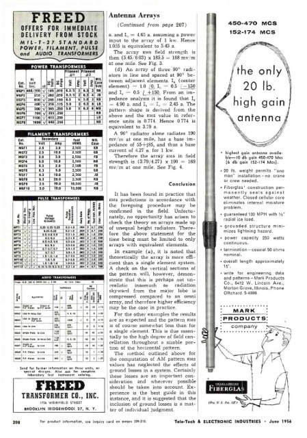
450-470 MCS<br />
152-174 MCS<br />
the only<br />
20 Ib.<br />
high gain<br />
antenna<br />
highest gain antenna available-IO<br />
db gain 450 -470 Ws<br />
(6 db gain 152 -174 Mcs).<br />
20 Ib. weight permits "one<br />
man" installation -no crane<br />
or crew needed.<br />
Fiberglas* construction permanently<br />
seals against<br />
weather. Closed cellular core<br />
eliminates internal moisture<br />
problem.<br />
guaranteed 100 MPH with 1/2"<br />
radial ice load.<br />
grounded structure minimizes<br />
lightning hazard.<br />
power capacity 250 watts<br />
continuous.<br />
termination -coaxial 50 ohms<br />
nominal.<br />
overall length approximately<br />
15'.<br />
write for engineering data<br />
and patterns -Mark Products<br />
Co., 6412 W. Lincoln Ave.,<br />
Morton Grove, Illinois. Phone<br />
ORchard 5 -4999.<br />
MARK<br />
PRODUCTS<br />
company<br />
OWE ..CONINING<br />
FIBERGLAS<br />
208 For product information, use inquiry card on pages 209-210.<br />
Tele -Tech & ELECTRONIC INDUSTRIES June 1956


