

TELE-TECH & - AmericanRadioHistory.Com
TELE-TECH & - AmericanRadioHistory.Com
TELE-TECH & - AmericanRadioHistory.Com

You also want an ePaper? Increase the reach of your titles
YUMPU automatically turns print PDFs into web optimized ePapers that Google loves.
tion that would be reliable under<br />
conditions of signal variation resulting<br />
from interference at the<br />
D/F antenna between direct and<br />
reflected rays.<br />
System Description<br />
The system installation plan for<br />
the Radio Direction Finder AN /-<br />
CRD-6 is shown in Fig. 1. The<br />
facility provides bearing information<br />
automatically and essentially<br />
instantaneously on CW, voice or<br />
tone modulated signals on any one<br />
of 10<br />
preset crystal controlled<br />
channels of the 1750 available<br />
channels in the 225 to 400 MC<br />
frequency range. Bearing display<br />
is accomplished by means of a<br />
pointer type indicator.<br />
The system comprises a local<br />
station and one to four remote<br />
stations. The local station consists<br />
of two identical direction finding<br />
antennas mounted on separate<br />
masts at different heights to pro -<br />
vide height diversity with respect<br />
to the received signal, a target<br />
antenna to permit system self -check<br />
and alignment, and a prefabricated<br />
shelter containing the local station<br />
electronic components. The shelter<br />
contains a comparator to determine<br />
and select the antenna in the<br />
stronger r -f field, a multi- channel<br />
crystal controlled radio receiver, a<br />
local bearing indicator, a local control<br />
unit, and a multi -channel crystal<br />
controlled target transmitter.<br />
Each remote station consists of a<br />
remote control unit and an azimuth<br />
indicator identical to the local indicator.<br />
These units are designed for<br />
installation into existing and planned<br />
control tower consoles and also<br />
for standard rack installation. The<br />
master remote station which may<br />
be located up to five miles from the<br />
D/F site, exercises complete control<br />
of the system over a four wire<br />
D/F ANTENNA<br />
\'<br />
ROTAI NG<br />
REFLECTOR<br />
30 "<br />
MODULATED<br />
-"' "'<br />
I<br />
MOTOR<br />
1800<br />
RPM<br />
RF<br />
STATIONARY<br />
DIPOLE<br />
RADIO<br />
RECEIVER<br />
P RASEME TER<br />
30n. QUADRATURE<br />
2 0 REFERENCE REFERENCE VOLTAGES<br />
VOLTAGE<br />
GENERATE<br />
telephone type cable. A total of<br />
three additional remote stations<br />
that also exercise complete control<br />
of the system may be employed in<br />
parallel with the master station.<br />
The most distant parallel remote<br />
station can be located 10,000 ft. or<br />
less from the master remote<br />
station.<br />
When furnished for permanent<br />
fixed station operation, without a<br />
prefabricated shelter and submersion<br />
proof transit cases, identical<br />
equipment is known as Radio<br />
Direction Finder AN /FRD -2.<br />
AMPLIFIER<br />
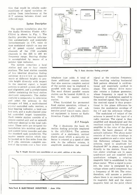
Fig. 3: Basic direction finding principle<br />
D/F Principle<br />
Fig. 3 illustrates the basic direction<br />
finding principle employed<br />
in the AN /CRD -6. The antenna<br />
consists of a stationary, vertical<br />
dipole about which a parasitic reflector<br />
is rotated at a speed of 1800<br />
RPM. As the reflector rotates, it<br />
amplitude modulates the received<br />
Fig. 4: Height diversity uses cancellation at one point, addition at the other<br />
REFLECTED ENERGY AT<br />
ANTENNA SITE IS SMALL<br />
COMPARED TO ENERGY OF<br />
THE DIRECT SIGNAL AT<br />
THE LOWER ANTENNA<br />
DIRECT AND REFLECTED<br />
SIGNALS CANCEL AT<br />
HIGH ANTENNA<br />
DIRECT AND REFLECTED<br />
SIGNALS ADD AT LOWER<br />
ANTENNA<br />
h<br />
30<br />
signal at the rotation frequency.<br />
The resulting rotating horizontal<br />
field pattern obtained is unidirectional<br />
and essentially cardiod in<br />
shape. The reflector drive motor<br />
also rotates a 2 -phase generator,<br />
whose frequency is equal to the<br />
frequency of modulation applied to<br />
the received signal. The bearing of<br />
the received signal is thus proportional<br />
to the phase difference between<br />
the modulation envelope of<br />
the r -f and the reference voltage.<br />
The modulated r -f output of the<br />
antenna is passed to the input of a<br />
radio receiver. The signal is then<br />
amplified and demodulated and the<br />
resultant output is fed through an<br />
amplifier to the rotor of the phase<br />
meter, the basic element of the<br />
azimuth indicator. The phase meter<br />
consists of two stator windings in<br />
space quadrature and a rotor winding.<br />
Reference voltages from the<br />
antenna, equal in amplitude but<br />
displaced 90° in phase, are applied<br />
directly to the stators. Since the<br />
two stator windings are in space<br />
quadrature and are supplied with<br />
quadrature voltages, a rotating<br />
magnetic field is established in the<br />
phase meter. When a signal is present,<br />
the rotor is energized by a<br />
voltage whose useful component has<br />
a frequency of 30 CPS. The rotor,<br />
therefore, will assume a position<br />
where there is no reaction between<br />
its magnetic field and the stator<br />
magnetic field (at the point where<br />
;Tel, -Tech & ELECTRONIC INDUSTRIES June 1956 91


