

TELE-TECH & - AmericanRadioHistory.Com
TELE-TECH & - AmericanRadioHistory.Com
TELE-TECH & - AmericanRadioHistory.Com

Create successful ePaper yourself
Turn your PDF publications into a flip-book with our unique Google optimized e-Paper software.
Ì<br />
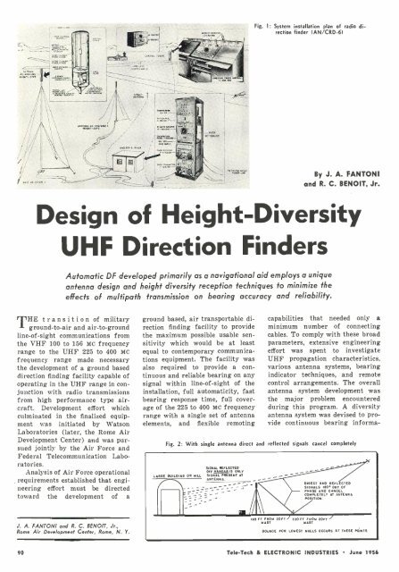
Fig. l: System installation plan of radio direction<br />
finder IAN /CRD -61<br />
--<br />
`;<br />
ä:;.<br />
x.r:ñ="<br />
..,, .. AM.M 1<br />
By J. A. FANTONI<br />
and R. C. BENOIT, Jr.<br />
Design of Height -Diversity<br />
UHF Direction Finders<br />
Automatic DF developed primarily as a navigational aid employs a unique<br />
antenna design and height diversity reception techniques to minimize the<br />
effects of multipath transmission on bearing accuracy and reliability.<br />
THE transition of military<br />
ground -to -air and air -to- ground<br />
line -of -sight communications from<br />
the VHF 100 to 156 Mc frequency<br />
range to the UHF 225 to 400 MC<br />
frequency range made necessary<br />
the development of a ground based<br />
direction finding facility capable of<br />
operating in the UHF range in conjunction<br />
with radio transmissions<br />
from high performance type aircraft.<br />
Development effort which<br />
culminated in the finalized equipment<br />
was initiated by Watson<br />
Laboratories (later, the Rome Air<br />
Development Center) and was pursued<br />
jointly by the Air Force and<br />
Federal Telecommunication Laboratories.<br />
Analysis of Air Force operational<br />
requirements established that engineering<br />
effort must be directed<br />
toward the development of a<br />
ground based, air transportable direction<br />
finding facility to provide<br />
the maximum possible usable sensitivity<br />
which would be at least<br />
equal to contemporary communications<br />
equipment. The facility was<br />
also required to provide a continuous<br />
and reliable bearing on any<br />
signal within line -of -sight of the<br />
installation, full automaticity, fast<br />
bearing response time, full coverage<br />
of the 225 to 400 MC frequency<br />
range with a single set of antenna<br />
elements, and flexible remoting<br />
capabilities that needed only a<br />
minimum number of connecting<br />
cables. To comply with these broad<br />
parameters, extensive engineering<br />
effort was spent to investigate<br />
UHF propagation characteristics,<br />
various antenna systems, bearing<br />
indicator techniques, and remote<br />
control arrangements. The overall<br />
antenna system development was<br />
the major problem encountered<br />
during this program. A diversity<br />
antenna system was devised to provide<br />
continuous bearing informa-<br />
Fig. 2: With single antenna direct and reflected signals cancel completely<br />
LARGE BUILDING OR HILL<br />
SIGNAL REFLECTED<br />
OFF NANGARIS ONLY<br />
SIGNAL PRESENT AT<br />
ANTENNA.<br />
DIRECT AND REFLECTED<br />
SIGNALS 180. OUT OF<br />
PHASE AND CANCEL<br />
COMPLETELY AT ANTENNA<br />
POSITION.<br />
J. A. SANTON/ and R. C. BENOÎT, Jr.,<br />
Rome Air Development Center, Rome, N. Y.<br />
65 FT FROM 20FT - 330 FT FROM 20FT<br />
MAST<br />
MAST<br />
BOUNCE FOR LOWEST NULLS OCCURS AT THESE POINTS<br />
90 Tele -Tech & ELECTRONIC INDUSTRIES June 1956


