

TELE-TECH & - AmericanRadioHistory.Com
TELE-TECH & - AmericanRadioHistory.Com
TELE-TECH & - AmericanRadioHistory.Com

Create successful ePaper yourself
Turn your PDF publications into a flip-book with our unique Google optimized e-Paper software.
Frequency<br />
700 CPS<br />
70 KC<br />
7 MC<br />
700 MC<br />
By C. A. KERNS<br />
Table I<br />
Skin Depth<br />
(mils)<br />
Surface Resistance<br />
lµ62 /square)<br />
Sample<br />
Table<br />
Il: r -f Resistance of Various Materials<br />
Relative loss<br />
at 12 MC<br />
Relative loss<br />
at 40 MC<br />
100 7<br />
Aluminum 25 1.3 1.5<br />
Alloy 24S 3.0 2.2<br />
10 70 Alloy 61S 1.9 1.8<br />
1 700 Brass 2.1 2.5<br />
0.1 7,000<br />
Copper<br />
Soft<br />
Hard<br />
1.0<br />
1.0<br />
1.0<br />
1.0<br />
OFHC 1.0 1.0<br />
Phosphorus- deoxidized 1.3 1.3<br />
Beryllium copper 4.2 3.6<br />
Phosphor bronze 4.8 4.4<br />
Graphite 63.0 58.0<br />
Lead 7.2 6.1<br />
Manganin 11.0 9.5<br />
Molybdenum 2.7 2.3<br />
Solder (Soft) 6.4 5.6<br />
Iron Mild steel 74.0 71.0<br />
Q. A. KERNS, Radi-<br />
Auto -body<br />
85.0<br />
65.0<br />
ation Lab., Dept.<br />
Inconel<br />
19.2<br />
16.5<br />
of Physics, Univ. S.S. 302 8.0 14.7<br />
of Calif., Berkeley, Silver (99.7% pure) 1.1 1.1<br />
Calif. Plating 1.0 1.0<br />
Zinc Plated chassis 27.4 2.8<br />
Galvanized iron 4.4 2.7<br />
Chromium Plating (UCRL) 11.0<br />
Tungsten 2.7 2.3<br />
conductivity of the thin surface layer<br />
in which current flows. In general<br />
the conductivity must be measured<br />
at the frequency of interest rather<br />
than by extrapolation, since the<br />
properties may vary considerably<br />
with depth. The eddy -current bridge<br />
was designed to measure the conductivity<br />
of sample surfaces at an<br />
operating frequency, the end in view<br />
being the production of low -loss surfaces.<br />
A sample of oxygen -free high -<br />
conductivity copper (OFHC) was<br />
used as a standard. Although most of<br />
the original work was done with<br />
copper, the bridge is not restricted to<br />
materials of high conductivity. In<br />
fact, once the problem has been<br />
solved for good conductors, the<br />
measuring technique is simple for<br />
lossy materials such as graphite.<br />
Conductor Surface Parameters<br />
An appreciation of the magnitudes<br />
involved in measuring skin loss for<br />
RO<br />
CHOKE<br />
H. 200 V. PK. R -F<br />
copper can be gained by reviewing<br />
Table I. Surface resistance and skin -<br />
depth values given are calculated<br />
from the standard formulas.<br />
Surface resistance is the parameter<br />
to be measured. The general method<br />
is to produce a surface current of<br />
the order of a few amperes per unit<br />
width and to measure the resulting<br />
IR drop across a few unit lengths.<br />
Required current in the driving loop<br />
is then several amperes, and the loss<br />
signal measured in the pickup loop<br />
is of the order of mv., for copper at<br />
10 Me. Signals in the pickup loop are<br />
directly proportional to surface loss<br />
of the sample for the idealized case<br />
of a pickup loop buried in the surface.<br />
Principle of Operation<br />
Eddy currents are induced in the<br />
sample surface by passing a current<br />
of the desired frequency through the<br />
driving loop positioned a radius<br />
DRIVING<br />
Li) /4 LOOP LOOP<br />
/4 A<br />
30 CPS<br />
SWITCHING<br />
1#06Von<br />
-. SCOPE<br />
PICKUP<br />
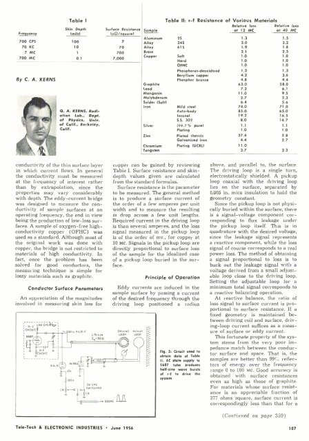
Fig. 3: Circuit used to<br />
obtain data of Table<br />
Il. AC plate supply to<br />
5687 tube produces<br />
half -sine wave bursts<br />
of r -f to drive the<br />
system<br />
above, and parallel to, the surface.<br />
The driving loop is a single turn,<br />
electrostatically shielded. A pickup<br />
loop coaxial with the driving loop<br />
lies on the surface, separated by<br />
0.005 in. mica insulation to hold the<br />
geometry constant.<br />
Since the pickup loop is not physically<br />
buried within the surface, there<br />
is a signal -voltage component corresponding<br />
to flux leakage under<br />
the pickup loop itself. This is in<br />
quadrature with the desired voltage,<br />
since the leakage signal represents<br />
a reactive component, while the loss<br />
signal of course corresponds to a real<br />
power loss. The method of obtaining<br />
a signal proportional to loss is to<br />
buck out the leakage signal with a<br />
voltage derived from a small adjustable<br />
loop close to the driving loop.<br />
Setting the adjustable loop for a<br />
minimum total signal corresponds to<br />
a reactive balancing operation.<br />
At reactive balance, the ratio of<br />
loss signal to surface current is proportional<br />
to surface resistance. If a<br />
fixed geometry is maintained between<br />
driving coil and surface, driving<br />
-loop current suffices as a measure<br />
of surface or eddy current.<br />
This fortunate property of the system<br />
stems from the very poor impedance<br />
match between the conductor<br />
surface and space. That is, the<br />
samples are better than 99 %ó reflectors<br />
of energy over the frequency<br />
range 0 to 100 Mc. Good accuracy is<br />
obtained with surface resistances<br />
even as high as those of graphite.<br />
For materials whose surface resistance<br />
is an appreciable fraction of<br />
377 ohms /square, surface current is<br />
correspondingly less than that for a<br />
(Continued on page 359)<br />
Tele -Tech & ELECTRONIC INDUSTRIES June 1956<br />
107


