

TELE-TECH & - AmericanRadioHistory.Com
TELE-TECH & - AmericanRadioHistory.Com
TELE-TECH & - AmericanRadioHistory.Com

You also want an ePaper? Increase the reach of your titles
YUMPU automatically turns print PDFs into web optimized ePapers that Google loves.
Getting back to the front end of<br />
the i -f amplifier, the low -noise preamplifier<br />
uses a type 416B triode in<br />
a grounded -grid circuit. The i -f<br />
noise figure is about 5 db, and the<br />
overall receiver noise figure is<br />
about 19 db. An AFC system is<br />
utilized that is relatively simple<br />
and has proved quite effective. This<br />
is a dual -channel system, in which<br />
two narrow -band i -f amplifier channels<br />
are used, each with a bandwidth<br />
of 10 MC. One of these channels<br />
is tuned to 20 MC below the<br />
center frequency of the i -f amplifier,<br />
and the other is tuned 20 MC<br />
above the center frequency. These<br />
amplifiers effectively sample the<br />
energy content of the spectrum of<br />
the i -f pulse on either side of its<br />
peak. When the receiver is properly<br />
tuned, the i -f spectrum will<br />
produce equal outputs in the two<br />
channels. Any unbalance in the<br />
outputs of the two channels signifies<br />
improper tuning. This unbalance<br />
is detected and used to correct<br />
the local -oscillator tuning.<br />
The remainder of the receiver<br />
contains a distributed detector,<br />
video amplifier and line drivers,<br />
gain control circuits, and a sensitivity-<br />
time -control circuit.<br />
In the PPI, a special 16 -inch<br />
cathode -ray tube preserves the<br />
high -resolution capabilities of the<br />
system. Although the tube has no<br />
unusual or unique characteristics,<br />
it does represent a combination of<br />
the best known techniques to give<br />
high resolution for this application.<br />
The resolution obtainable is better<br />
than 1000 lines /diameter.<br />
Instead of the usual servo system<br />
to drive the rotating deflection<br />
yoke in step with the antenna, a<br />
simplified synchronous motor drive<br />
system has been devised. In this<br />
system, an alternator is geared to<br />
the antenna at about 80 times the<br />
speed of the antenna. The 80 -cycle<br />
voltage from the alternator is used,<br />
after amplification, to excite a synchronous<br />
motor in the PPI that<br />
drives the deflection yoke through<br />
a corresponding gear train. The<br />
system is designed to hold the deflection<br />
yoke within -±-0.1 degree<br />
of the relative position of the antenna<br />
and hold this accuracy in the<br />
face of the greatest accelerations<br />
to be expected from the antenna.<br />
This system has many possible<br />
(Continued on page 186)<br />
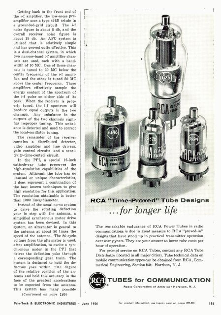
RCA "Time- Proved" Tube Designs<br />
...for longer life<br />
The remarkable endurance of RCA Power Tubes in radio<br />
communications is due in great measure to RCA "proved -in"<br />
designs that have stood up in practical transmitter operation<br />
over many years. They are your answer to lower tube costs per<br />
hour of operation.<br />
For prompt service on RCA Tubes, .contact any RCA Tube<br />
Distributor (located in all major cities). Tube technical data on<br />
mobile communication types can be obtained from RCA, <strong>Com</strong>merical<br />
Engineering, Section HOP. Harrison, N. J.<br />
TUBES for COMMUNICATION<br />
Radio Corporation of America Harrison, N. J,<br />
Tele -Tech & ELECTRONIC INDUSTRIES June 1956<br />
For product information, use inquiry cord on pages 209 -210. 185


