

TELE-TECH & - AmericanRadioHistory.Com
TELE-TECH & - AmericanRadioHistory.Com
TELE-TECH & - AmericanRadioHistory.Com

You also want an ePaper? Increase the reach of your titles
YUMPU automatically turns print PDFs into web optimized ePapers that Google loves.
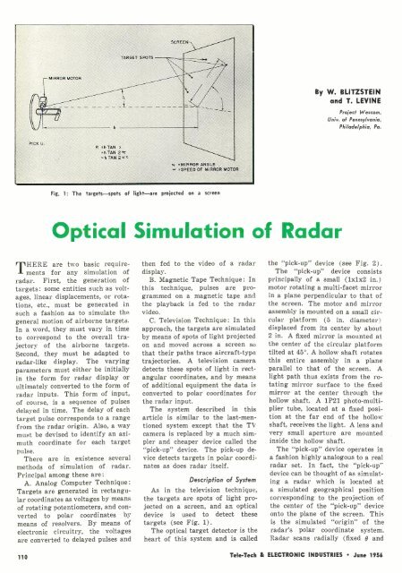
MIRROR MOTOR<br />
,<br />
SCREEN<br />
TARGET SPOTS<br />
i<br />
By W. BLITZSTEIN<br />
and T. LEVINE<br />
Project Wescom,<br />
Univ. of Pennsylvania,<br />
Philadelphia, Pa.<br />
PICK U.<br />
R =h TAN<br />
a<br />
=h TAN 2°c<br />
=h TAN 2'."<br />
a 'MIRROR ANGLE<br />
' =SPEED OF MIRROR MOTOR<br />
Fig. 1: The targets -spots of light -are projected on a screen<br />
Optical Simulation of Radar<br />
THERE are two basic requirements<br />
for any simulation of<br />
radar. First, the generation of<br />
targets: some entities such as voltages,<br />
linear displacements, or rotations,<br />
etc., must be generated in<br />
such a fashion as to simulate the<br />
general motion of airborne targets.<br />
In a word, they must vary in time<br />
to correspond to the overall trajectory<br />
of the airborne targets.<br />
Second, they must be adapted to<br />
radar -like display. The varying<br />
parameters must either be initially<br />
in the form for radar display or<br />
ultimately converted to the form of<br />
radar inputs. This form of input,<br />
of course, is a sequence of pulses<br />
delayed in time. The delay of each<br />
target pulse corresponds to a range<br />
from the radar origin. Also, a way<br />
must be devised to identify an azimuth<br />
coordinate for each target<br />
pulse.<br />
There are in existence several<br />
methods of simulation of radar.<br />
Principal among these are:<br />
A. Analog <strong>Com</strong>puter Technique:<br />
Targets are generated in rectangular<br />
coordinates as voltages by means<br />
of rotating potentiometers, and converted<br />
to polar coordinates by<br />
means of resolvers. By means of<br />
electronic circuitry, the voltages<br />
are converted to delayed pulses and<br />
then fed to the video of a radar<br />
display.<br />
B. Magnetic Tape Technique: In<br />
this technique, pulses are programmed<br />
on a magnetic tape and<br />
the playback is fed to the radar<br />
video.<br />
C. Television Technique: In this<br />
approach, the targets are simulated<br />
by means of spots of light projected<br />
on and moved across a screen so<br />
that their paths trace aircraft -type<br />
trajectories. A television camera<br />
detects these spots of light in rectangular<br />
coordinates, and by means<br />
of additional equipment the data is<br />
converted to polar coordinates for<br />
the radar input.<br />
The system described in this<br />
article is similar to the last -mentioned<br />
system except that the TV<br />
camera is replaced by a much simpler<br />
and cheaper device called the<br />
"pick-up" device. The pick -up device<br />
detects targets in polar coordinates<br />
as does radar itself.<br />
Description of System<br />
As in the television technique,<br />
the targets are spots of light projected<br />
on a screen, and an optical<br />
device is used to detect these<br />
targets (see Fig. 1).<br />
The optical target detector is the<br />
heart of this system and is called<br />
the "pick-up" device (see Fig. 2).<br />
The "pick-up" device consists<br />
principally of a small (1x1x2 in.)<br />
motor rotating a multi -facet mirror<br />
in a plane perpendicular to that of<br />
the screen. The motor and mirror<br />
assembly is mounted on a small circular<br />
platform (5 in. diameter)<br />
displaced from its center by about<br />
2 in. A fixed mirror is mounted at<br />
the center of the circular platform<br />
tilted at 45 °. A hollow shaft rotates<br />
this entire assembly in a plane<br />
parallel to that of the screen. A<br />
light path thus exists from the rotating<br />
mirror surface to the fixed<br />
mirror at the center through the<br />
hollow shaft. A 1P21 photo- multiplier<br />
tube, located at a fixed position<br />
at the far end of the hollow<br />
shaft, receives the light. A lens and<br />
very small aperture are mounted<br />
inside the hollow shaft.<br />
The "pick-up" device operates in<br />
a fashion highly analogous to a real<br />
radar set. In fact, the "pick-up"<br />
device can be thought of as simulating<br />
a radar which is located at<br />
a simulated geographical position<br />
corresponding to the projection of<br />
the center of the "pick-up" device<br />
onto the plane of the screen. This<br />
is the simulated "origin" of the<br />
radar's polar coordinate system.<br />
Radar scans radially (fixed O and<br />
110<br />
Telle-Tech & ELECTRONIC INDUSTRIES June 1956


