

TELE-TECH & - AmericanRadioHistory.Com
TELE-TECH & - AmericanRadioHistory.Com
TELE-TECH & - AmericanRadioHistory.Com

Create successful ePaper yourself
Turn your PDF publications into a flip-book with our unique Google optimized e-Paper software.
tuning facilities; minimum size;<br />
comparable resettability; similar<br />
range of permissible output loads;<br />
freedom from r -f or control circuit<br />
instability; and good dynamic<br />
regulation of power supply. A<br />
study of existing linear amplifiers<br />
led to the conclusion that a new<br />
concept of tank circuit was necessary<br />
to meet these objectives with<br />
minimum complexity.<br />
Tank Circuit Design<br />
A study of existing tubes and<br />
tank circuit configurations resulted<br />
in the conclusion that a<br />
grounded grid single stage amplifier<br />
with a pi type plate tank circuit<br />
was desirable. To obtain the<br />
desired tuning range of 4 -26.5 Mc<br />
a single pi section would require<br />
varying the series inductance as<br />
well as the shunt capacitance elements.<br />
Previous experience with<br />
sliding contacts and tap switches<br />
at this power level made it desirable<br />
to seek some other means<br />
for extending the tuning range of<br />
the tank which would reduce the<br />
maintenance a n d resettability<br />
problems which such contacts and<br />
switches, carrying circulating current,<br />
have experienced in the past.<br />
By taking advantage of the low<br />
minimum capacitances of modern<br />
vacuum variable capacitors; it<br />
was possible to devise a pi type<br />
tank circuit which utilizes fixed<br />
inductances, has no switches or<br />
sliding contacts which carry circulating<br />
tank current, and in<br />
Fig. 2: Prototype design of amplifier. R -f and<br />
rectifier cabinets shown require floor space<br />
6 ft. wide by 3 ft. deep<br />
"9a<br />
-<br />
é<br />
o<br />
á<br />
o<<br />
z<br />
o<br />
20<br />
- 30<br />
ó 40<br />
E<br />
o<br />
w 50<br />
ó<br />
60<br />
70 -16<br />
IIÏIIIIII1<br />
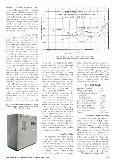
LINEAR<br />
INPUT<br />
POWER<br />
TONES<br />
AMPLIFIER<br />
TYPICAL TWO -TONE DISTORTION CHARACTERISTICS<br />
.<br />
?TH<br />
-14 -12 -10 -<br />
11000 1575<br />
CYCLES<br />
CYCLES<br />
3RD ORDER<br />
/ i-- __ 5TH ORDER<br />
-<br />
ORDER<br />
RELATIVE OUTPUT TONE- do<br />
i<br />
Iy_rr<br />
Fig. 3: Distortion data. Further improvements have<br />
reduced third order distortion products even further<br />
which the resettability is determined<br />
primarily by precision lead<br />
screws in the capacitors. This<br />
tank circuit, along with some of<br />
the associated circuits, is shown<br />
in Fig. 1. At the lowest operating<br />
frequency. C -8, C -9, and C -10 are<br />
adjusted to minimum capacitance,<br />
effectively removing them from the<br />
circuit. The remaining circuit<br />
consists of the tuning capacitor<br />
C -7; coils L -4, L -5, L -6 and L -7;<br />
and loading capacitance C -11. Relay<br />
K -5 is closed, connecting the<br />
output circuit to the loading capacitance.<br />
As frequency is increased<br />
C -10, C -9 and C -8 successively<br />
become the loading capacitance<br />
and vacuum switches K -4,<br />
K -3 and K -2 transfer the output<br />
circuit. That portion of the tank<br />
circuit which is not used at any one<br />
time is effectively removed by adjusting<br />
its capacitance value to<br />
maximum. The input circuit consists<br />
of a relatively low Q parallel<br />
tuned circuit to adjust input impedance<br />
of the amplifier to provide<br />
a suitable termination for the<br />
driving transmitters.<br />
Amplifier Tube<br />
For improved distortion, it was<br />
decided to operate the LD -T2<br />
driver at 2.5 kw peak output or<br />
less. To obtain desired output, a<br />
power gain in the linear amplifier<br />
of the order of 15 was, therefore,<br />
necessary. This dictated the<br />
choice of a relatively high mu<br />
íc 3<br />
n<br />
7 __<br />
i<br />
I_ _<br />
tube. Other desirable characteristics<br />
for the tube included small<br />
size, air cooling with minimum air<br />
volume, relatively high plate dissipation,<br />
and long life. Two Type<br />
6423 coaxial terminal triodes were<br />
selected for use in the amplifier.<br />
General characteristics of these<br />
tubes are given below:<br />
Type 6423 Triode<br />
Filament Voltage<br />
Filament Current<br />
Amplification Factor<br />
Interelectrode Capacity<br />
Grid -plate<br />
Grid -filament<br />
Plate filament<br />
Max. de Plate Voltage<br />
Max. dc Grid Voltage<br />
Max. dc Plate Current<br />
Max. Plate Input<br />
Max. Plate Dissipation<br />
Approximate weight<br />
Max. diameter<br />
Height<br />
62 v.<br />
81 a.<br />
90<br />
25 µµf<br />
82 µµf<br />
1.5 µµf<br />
1.1,500 v.<br />
-1400 v.<br />
2.5 a.<br />
so kw<br />
12.5 kw<br />
18 lbs.<br />
4 -% in.<br />
15-9/16 in.<br />
Prototype Linear Amplifier<br />
A prototype linear amplifier has<br />
been constructed for full scale<br />
confirmation of excellent results<br />
obtained in testing a 3 kw breadboard<br />
model of the pi tank circuit.<br />
This prototype, shown in Fig. 2,<br />
consists of the r -f and rectifier<br />
cabinets with a total floor space<br />
6 ft. wide and 3 ft. deep. Exhaustive<br />
tests isolated and eliminated<br />
parasitic oscillation and resulted<br />
in circuit stability permitting<br />
full plate voltage to be applied<br />
at zero grid bias with no<br />
tendency toward self -oscillation.<br />
(Continued on page 154)<br />
Tele -Tech & ELECTRONIC INDUSTRIES June 1956<br />
109


