

TELE-TECH & - AmericanRadioHistory.Com
TELE-TECH & - AmericanRadioHistory.Com
TELE-TECH & - AmericanRadioHistory.Com

You also want an ePaper? Increase the reach of your titles
YUMPU automatically turns print PDFs into web optimized ePapers that Google loves.
for<br />
GUIDED<br />
MISSILES<br />
Encapsulated multiple -<br />
tap Type 384. Stabilised<br />
for rugged environments.<br />
for<br />
LABORATORY<br />
DEVELOPMENT<br />
Variable step Type 382.<br />
Total delay, 1.1 ps in<br />
0.02 ps steps. Reflections<br />
less than 10%.<br />
for COLOR TV<br />
Distributed-Constant Type<br />
T 30036. Phase characteristics<br />
linear within<br />
5% to 4 mc.<br />
Shallcross<br />
DELAY LINES<br />
Shallcross<br />
for COMMERCIAL<br />
INSTRUMENTATION<br />
Enclosed Type T 30030. Total<br />
delay, 1.5 tts with 0.05 ps taps.<br />
for COMPUTERS<br />
Miniature encapsulated<br />
plug -in Type T 30009.<br />
Only 1 r/ " wide by 11/2"<br />
high.<br />
for RADAR<br />
Multiple -section, open<br />
Type 380. Total delay,<br />
0.33 µs with 0.04 µs<br />
tops.<br />
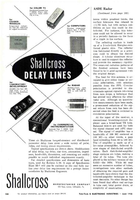
These six Shallcross lumped- constant and distributed -<br />
parameter delay lines cover a wide variety of pulse,<br />
video, and timing circuit requirements.<br />
Typical specifications are shown above. Modifications<br />
of total delay, tap delay, rise time, attenuation, impedance,<br />
bandwidth, dimensions, and mounting are readily<br />
possible to match individual requirements exactly.<br />
For detailed specifications and dimensions of basic<br />
types, send for Bulletin L -38. A copy of Specification<br />
Sheet SS -7 will also be enclosed so you may fully outline<br />
your delay line requirements for a prompt recommendation<br />
by Shallcross Engineers.<br />
MANUFACTURING COMPANY<br />
518 Pusey Avenue, Collingdale, Pa.<br />
ASDE Radar<br />
(Continued from page 183)<br />
tenna within practical limits, the<br />
surface tolerance was relaxed to<br />
±1/32 inch, but with certain conditions<br />
on how this could be distributed.<br />
For instance, this tolerance<br />
could not be allowed to occur<br />
in a periodic fashion -in the form<br />
of a ripple in the surface.<br />
The reflecting surface is made<br />
up of a 2- inch -thick fiberglas -reinforced<br />
plastic skin. The reflector<br />
was fabricated directly on a precision<br />
mold to obtain the desired<br />
shape. A tubular aluminum structure<br />
is used to support the reflector<br />
and provide the necessary rigidity.<br />
The measured radiation patterns of<br />
the finished antenna have been<br />
found to be in good agreement with<br />
the original design.<br />
The feed for this antenna is arranged<br />
to give either linear or circular<br />
polarization, with selection<br />
possible from the PPI. Circular<br />
polarization is provided to discriminate<br />
against signals returning<br />
from rain drops, a technique that<br />
has proved very effective for other<br />
radar sets. Although no quantitative<br />
measurements have been made,<br />
a pronounced reduction of the signal<br />
return from rain has been observed<br />
when the feed is switched to<br />
circulation polarization.<br />
At the input of the receiver, a<br />
conventional branching- circuit duplexer<br />
uses a broad -band TR tube.<br />
Balanced mixers are used for both<br />
the signal channel and AFC channel.<br />
The signal i -f amplifier has a<br />
bandwidth of 100 MC centered at<br />
130 MC -in other words, a pass<br />
band extending from 80 to 180 MC.<br />
The i -f amplifier is made up of a<br />
low -noise preamplifier, followed by<br />
nine stages of distributed amplification.<br />
Each distributed -amplifier<br />
stage contains six tubes, making a<br />
total of 54 tubes. The tube em-<br />
ployed is the military version of the<br />
6AK5 -the 5654. While 54 may<br />
seem an excessive number of tubes,<br />
investigations into other methods<br />
of obtaining the required gain and<br />
bandwidth have shown that the distributed-<br />
amplifier technique is the<br />
most desirable. No other design has<br />
been found that offers real savings<br />
in tube cost, total power drain, or<br />
simplicity of construction.<br />
184 For product information, use inquiry card on pages 209 -210.<br />
Tele -Tech & ELECTRONIC INDUSTRIES June 1956


