

TELE-TECH & - AmericanRadioHistory.Com
TELE-TECH & - AmericanRadioHistory.Com
TELE-TECH & - AmericanRadioHistory.Com

You also want an ePaper? Increase the reach of your titles
YUMPU automatically turns print PDFs into web optimized ePapers that Google loves.
Power Gain Meter<br />
(Continued from page 105)<br />
At high frequencies, the output impedance<br />
may have a phase angle of<br />
45° and higher. When a parallel<br />
tuned resonant tank is used, the effective<br />
capacitance of the output impedance<br />
is in parallel with the condenser<br />
of tank circuit. For a given<br />
frequency, the effective capacitance<br />
of the output impedance determines<br />
the maximum value of inductance of<br />
the tank circuit.) Two continuously<br />
variable resistances are desirable for<br />
r,, and r2 in Fig. 1, and proper mechanical<br />
coupling is required.<br />
Another point which demands attention<br />
in the circuit design concerns<br />
the dc bias connections. These<br />
paths should, if possible, have a high<br />
impedance for the ac signal, and low<br />
resistance for dc current. The blocking<br />
condenser in the ac path should<br />
have a capacitance large enough to<br />
let the lowest frequency encountered<br />
pass through without too much attenuation.<br />
This point is especially<br />
important on the input side of this<br />
instrument.<br />
The circuit described below is a<br />
power gain meter which can be used<br />
for pnp and npn junction transistors.<br />
This equipment in conjunction with a<br />
common laboratory signal generator<br />
and an ac millivoltmeter covers a<br />
frequency range from 10 xc to 3 Mc.<br />
In order to cover the radio frequencies<br />
without introducing too much<br />
error, the continuously variable resistances<br />
r,, rg r, and r,, described<br />
above are replaced by gauged<br />
stepped controls. The error introduced<br />
will be discussed later. The<br />
complete circuit is shown in Fig. 3.<br />
In this circuit the switch S2 is used<br />
for changing the bias current when<br />
the transistor circuit is changed from<br />
the grounded -base to the grounded -<br />
emitter connection. The switch S4 is<br />
used to select the polarity of the<br />
power supply for either pnp or npn<br />
transistors. The center position of S4<br />
is used to turn off the supply.<br />
The total resistance presented to<br />
the signal generator is 50 ohms.<br />
When the switch SL is at position I,<br />
r, is 5 ohms and rg is 50 ohms. If a<br />
signal voltage of 100 mv is applied<br />
across the 50 ohms, a Vg of 10 mv<br />
appears across the 5 ohm resistor.<br />
When a 50 ohms input resistance is<br />
connected in series with rg, a total<br />
of 100 ohms is now in shunt with r,<br />
which is 5 ohms. A slight change of<br />
Vg results. Let us neglect this small<br />
change of vg for the time being and<br />
(Continued on page 356)<br />
z<br />
O<br />
v<br />
z<br />
O<br />
u<br />
O<br />
`.'re<br />
RADIO COMMUNICATION SYSTEMS INFRARED DIGITAL <strong>TECH</strong>NIQUES DATA SYSTEMS<br />
SENIOR and INTERMEDIATE<br />
ELECTRONIC ENGINEERS<br />
<strong>TECH</strong>NICIANS AND ENGINEERING AIDES<br />
Stromberg- Carlson, a Division of General Dynamics Corporation, is located<br />
in the Finger Lakes region of upstate New York. In addition to providing a<br />
wide variety of challenging engineering opportunities, excellent salaries<br />
are offered with the finest working conditions in a modern electronics<br />
laboratory. Unusual recreational and educational facilities are available<br />
in this medium -sized progressive city, and fine residential areas are located<br />
within a mile of the plant. Because of the variety of its product line, which is<br />
approximately equally divided between military and civilian, Stromberg-<br />
Carlson offers a degree of stability and an opportunity for advancement<br />
unequalled in the industry. Openings:<br />
Radio <strong>Com</strong>munication Systems Data Systems Digital Techniques<br />
Microwave Circuits<br />
Mechanical Design Engineering<br />
Infrared<br />
Automatic Test Systems Countermeasures Navigational Systems<br />
Military Transistor Applications Radar Missile Guidance Systems<br />
Write or call collect:<br />
C. W. Finnigan, Chief Electronics Engineer<br />
STROMBERG- CARLSON COMPANY<br />
A DIVISION OF GENERAL DYNAMICS CORPORATION<br />
104 CARLSON ROAD, ROCHESTER 3, N. Y.<br />
S3äf1SV3W2131Nf1OD SNOI1VDIlddV 2O1SISNV2I AWs'IIl1W SW3ISAS 1531 DIIVWOIl1V<br />
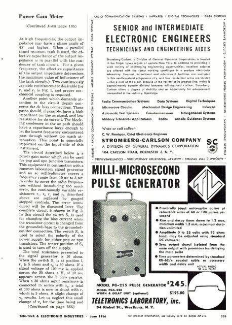
MILLI -MICROSECOND<br />
PULSE GENERATOR<br />
r="1<br />
MODEL PG-21 5<br />
MODEL PGA -220<br />
WIDTH & DELAY UNIT (optional)<br />
Practically ideal rectangular pulses at<br />
recurrence rates of 60 or 120 pulses per<br />
second<br />
Rise and decay times down to 1.2 nips,<br />
minimum width 1.2 mµs, maximum duration<br />
unlimited<br />
Amplitude 0 to 35 volts with 93 ohms<br />
load, may be adjusted using standard<br />
DC voltmeter<br />
Sync output signal isolated from the<br />
main output with provisions for delaying<br />
the main pulse<br />
Time parameters determined by standard<br />
RG- 62; -'µ coaxial cable or accessory<br />
width and delay unit<br />
PULSE GENERATOR $24 5 .<br />
5195.00<br />
<strong>TELE</strong>TRONICS LABORATORY, inc.<br />
54 Kinkel St., Westbury, N. Y.<br />
ACTUAL PHOTO<br />
50 mus PULSE<br />
Tele -Tech & ELECTRONIC INDUSTRIES June 1956<br />
For product information, use inquiry card on pages 209 -210 355


