

TELE-TECH & - AmericanRadioHistory.Com
TELE-TECH & - AmericanRadioHistory.Com
TELE-TECH & - AmericanRadioHistory.Com

You also want an ePaper? Increase the reach of your titles
YUMPU automatically turns print PDFs into web optimized ePapers that Google loves.
Color TV<br />
G/L/LI /L<br />
RADIO ®<br />
VACUUM ELECTRONIC COMPONENTS<br />
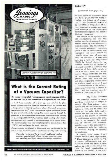
Establishing the current rating of o Jennings MMC 5000<br />
mmld vacuum capacitor using the J7002 Kilovoltmeter<br />
What is the Current Rating<br />
of a Vacuum Capacitor?<br />
The current ratings of all Jennings vacuum capacitors are established<br />
on our own 75 KW test transmitter at frequencies of 3 to 16 mc.<br />
At least three capacitors of a given type are tested in the plate<br />
circuit of this transmitter. They are mounted in still air, painted with<br />
a temperature indicating paint, and allowed to reach a maximum<br />
temperature of 175° F. -a conservative figure arbitrarily chosen<br />
to give a uniform basis for rating. The current passing through the<br />
capacitor at this temperature is computed from the voltage reading<br />
of a Jennings J1002 VTVM, which is a peak reading kilovoltmeter<br />
that reads directly through a frequency range of 20 cps to 50 mc.<br />
The maximum allowable operating temperature is much higher than<br />
175° F. and is different for each capacitor.<br />
Current ratings established in this manner can be doublec by the<br />
use of forced air cooling and at least quadrupled by water cooling.<br />
We invite you to send for a recently published catalog<br />
summary describing all of our vacuum capacitors, vacuum<br />
switches, and high voltage measuring equipment.<br />
IENNINGS RADIO MANUFACTURING CORP: 970 McLAUCHLIN AVE. P.O. BOX 1278 SAN JOSE 8, CALIF.<br />
(Continued from page 187)<br />
dividual cycles of subcarrier relative<br />
to the pulse position tends to<br />
confuse any judgment of symmetry.<br />
If the subcarrier lock -in is<br />
de- activated for the purpose of the<br />
test, however, a smooth and complete<br />
envelope of the chroma -signal<br />
transient response will become<br />
distinctly apparent.<br />
The choice of an optimum signal<br />
configuration for this test<br />
method can be determined within<br />
narrow limits by a few elementary<br />
considerations. The amplitudes of<br />
the chroma subcarrier envelopes<br />
(both I and Q components) and<br />
luminance (Y)<br />
pulse should be<br />
roughly equal and of adequate<br />
level. In addition, it is desirable<br />
that the pr i m a r y components<br />
(RGB) be formed simply by resistance<br />
matrixing of pulses of<br />
identical polarity to alleviate any<br />
suspicion of delay differentials in<br />
the special color bar signal<br />
source. These conditions are met<br />
by using a red -magenta background<br />
color field with the red<br />
and blue components proportioned<br />
to produce equal values of I and<br />
Q. An oscillogram of the primary<br />
component waveforms is shown in<br />
Fig. 1 and the resultant encoder<br />
output is illustrated in Fig. 2.<br />
The Unibar Generator<br />
The circuitry needed to generate<br />
these waveforms is simple in<br />
nature. The three primary pulse<br />
signals are derived from only two<br />
pulses, a wide one to define the<br />
limits of the color field and a<br />
narrow one for the gray bar. Inasmuch<br />
as the pattern is intended<br />
for oscilloscope examination only,<br />
there is no necessity for provision<br />
of vertical rate blanking.<br />
avoiding one of the complications<br />
of generating color -bar patterns<br />
for monitor display or systems<br />
transmission.<br />
A circuit using seven d u a l<br />
triodes satisfies this requirement.<br />
A block diagram is given in Fig.<br />
3, above. Adjustments are provided<br />
for width and delay of both<br />
pulses, as well as balancing controls<br />
for level equalization to<br />
eliminate all chroma in the gray<br />
188 For product information, use inquiry card on pages 209.210. Tele -Tech & ELECTRONIC INDUSTRIES June 1956


