

TELE-TECH & - AmericanRadioHistory.Com
TELE-TECH & - AmericanRadioHistory.Com
TELE-TECH & - AmericanRadioHistory.Com

You also want an ePaper? Increase the reach of your titles
YUMPU automatically turns print PDFs into web optimized ePapers that Google loves.
1 -<br />
P a e /rom an ¿njineer teb00%<br />
No. 36-Wien<br />
By J. F. SODARO<br />
Bridge Design<br />
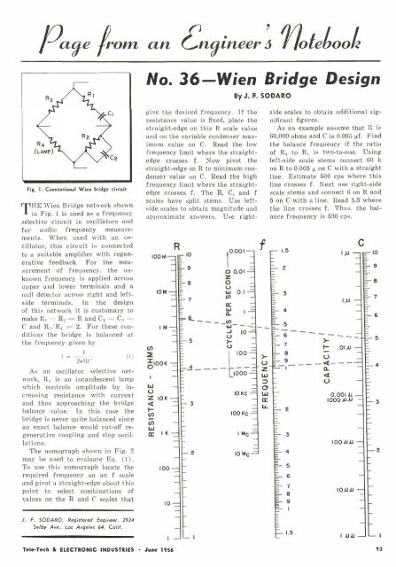
Fig. 1: Conventional Wien bridge circuit<br />
THE Wien Bridge network shown<br />
in Fig. 1 is used as a frequency<br />
selective circuit in oscillators and<br />
for audio frequency measurements.<br />
When used with an oscillator,<br />
this circuit is connected<br />
to a suitable amplifier with regen-<br />
erative feedback.<br />
For the mea-<br />
surement of frequency, the unknown<br />
frequency is applied across<br />
upper and lower terminals and a<br />
null detector across right and left -<br />
side terminals. In the design<br />
of this network it is customary to<br />
make RI= R_= R and C1 =C._=<br />
C and R;5 /Ra = 2. For these conditions<br />
the bridge is balanced at<br />
the frequency given by<br />
f =<br />
2,RC<br />
(I)<br />
As an oscillator selective network,<br />
R4 is an incandescent lamp<br />
which controls amplitude by increasing<br />
resistance with current<br />
and thus approaching the bridge<br />
balance value. In this case the<br />
bridge is never quite balanced since<br />
an exact balance would cut -off regenerative<br />
coupling and stop oscillations.<br />
The 'nomograph shown in Fig. 2<br />
may be used to evaluate Eq. (1) .<br />
To use this nomograph locate the<br />
required frequency on an f scale<br />
and pivot a straight -edge about this<br />
point to select combinations of<br />
values on the R and C scales that<br />
give the desired frequency. If the<br />
resistance value is fixed, place the<br />
straight -edge on this R scale value<br />
and on the variable condenser maximum<br />
value on C. Read the low<br />
frequency limit where the straightedge<br />
crosses f. Now pivot the<br />
straight -edge on R to minimum condenser<br />
value on C. Read the high<br />
frequency limit where the straightedge<br />
crosses f. The R, C, and f<br />
scales have split stems. Use left -<br />
side scales to obtain magnitude and<br />
approximate answers. Use right-<br />
ZOOM<br />
10M-<br />
1 M-<br />
10K -<br />
R<br />
10<br />
=9<br />
-= 8<br />
100 -<br />
10 -<br />
7<br />
FZ__ -<br />
t<br />
0.001 -<br />
o 0.01 =<br />
z O U -<br />
W 0.1 =<br />
N m -<br />
w<br />
I<br />
0_<br />
=<br />
= J 10 =<br />
=- 5 r<br />
- U<br />
_ 100 =<br />
=4<br />
- 3<br />
-2<br />
L1000 =<br />
IO Kc<br />
100 Kc =<br />
I<br />
MC =<br />
IOMc=<br />
f<br />
side scales to obtain additional significant<br />
figures.<br />
As an example assume that R is<br />
60,000 ohms and C is 0.005 µf. Find<br />
the balance frequency if the ratio<br />
of R.4 to RI is two -to -one. Using<br />
left -side scale stems connect 60 k<br />
on R to 0.005 µ on C with a straight<br />
line. Estimate 500 cps where this<br />
line crosses f. Next use right -side<br />
scale stems and connect 6 on R and<br />
5 on C with a line. Read 5.3 where<br />
the line crosses f. Thus, the balance<br />
frequency is 530 cps.<br />
- 1.5<br />
- 2<br />
3<br />
4<br />
5<br />
6<br />
- 7<br />
8<br />
- 9<br />
ç-1- - -<br />
C- 2<br />
= 3<br />
4<br />
6<br />
7<br />
r<br />
I-<br />
C<br />
IAJ --10<br />
.I,U -<br />
U -<br />
-Q----<br />
D-<br />
U<br />
.OI,IJ -<br />
0.001 AI 1000 ALU -<br />
I00AJAJ -<br />
10 ALU -<br />
=8<br />
- 7<br />
= 6<br />
5<br />
= 4<br />
-3<br />
-2<br />
J. F. SODARO, Registered Engineer, 2924<br />
Selby Ave., Los Angeles 64, Calif.<br />
TeleTech & ELECTRONIC INDUSTRIES June 1956<br />
- I<br />
1.5<br />
IAJAJ -<br />
- I<br />
93


