

TELE-TECH & - AmericanRadioHistory.Com
TELE-TECH & - AmericanRadioHistory.Com
TELE-TECH & - AmericanRadioHistory.Com

Create successful ePaper yourself
Turn your PDF publications into a flip-book with our unique Google optimized e-Paper software.
o.<br />
-.4111111..._<br />
'1.2<br />
i<br />
OE BELOW FREE SPACE RELD<br />
+20<br />
AIRPLANE AT<br />
I<br />
W<br />
+10<br />
-10<br />
11 `1``<br />
Fq<br />
'%<br />
I<br />
I<br />
I<br />
10,000'<br />
AT 20-<br />
ANTENNA<br />
ANTENNA AT 26,6'<br />
FREQ UENCY 394 MC,-<br />
a<br />
-<br />
V4<br />
"4T..<br />
- _<br />
-MAM<br />
=400 MCrS<br />
'<br />
' v/^`<br />
1=2% MC/5 ' i'<br />
-<br />
l -_<br />
f=230 MC9S 1.5'<br />
2.0'<br />
.0<br />
o -0 30 40 50 -<br />
DISTANCES IN MILES<br />
60 90 BO 90 00<br />
2^^_<br />
3 . 30 60 90 120 150 IBO 210 240 290 300 330 361<br />
DEGREES<br />
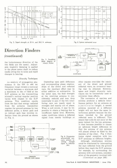
Fig. 5: Signal strength at 20 ft. and 26.6 ft. antennas<br />
Fig. 6: System instrument error<br />
Direction Finders<br />
(continued)<br />
the instantaneous direction of the<br />
two fields are the same). Adjustable<br />
magnetic damping is applied<br />
to the phase meter shaft to reduce<br />
needle swing due to noise and rapid<br />
changes in bearing.<br />
Fig. 7: Simplified<br />
block diagram of<br />
remote station<br />
SON. -, . ONNrrRaDlxr<br />
I Sou ,r..ND "°.<br />
OC<br />
CD,<br />
n<br />
MACS<br />
yss<br />
e<br />
.: _ Rñ a,.a<br />
!ACTON<br />
V<br />
REMOTE<br />
COQ *ROL<br />
V<br />
AZIMUTH<br />
INDICATOR<br />
i<br />
Diversity Techniques<br />
An analysis of propagation phenomena<br />
in the 225 to 400 MC<br />
frequency range reveals a continual<br />
variation between a minimum and<br />
a maximum in the r -f field at the<br />
D/F antenna as the transmitting<br />
aircraft's vertical angular position<br />
varies with respect to the D/F<br />
antenna. This condition results<br />
from the fact that energy radiated<br />
from the airborne transmitter<br />
reaches the ground antenna by two<br />
different paths, a direct path and<br />
an indirect path that involves reflection<br />
from the ground as shown<br />
in Fig. 2.<br />
COMPARATOR<br />
SIMPLIFIED BLOC% DIAGRAM<br />
Depending upon path difference<br />
and corresponding phase relationships<br />
of the direct and reflected<br />
rays, the resultant effect may be<br />
either additive or subtractive. In<br />
the latter case, the field strength<br />
at the receiving antenna is considerably<br />
reduced and may drop<br />
essentially to zero if the two interfering<br />
rays are nearly equal in<br />
strength and exactly out of phase.<br />
When a null occurs, it may be impossible<br />
to obtain a bearing due to<br />
insufficient signal level. Moreover,<br />
under conditions where a reflected<br />
signal from nearby buildings or<br />
TUATA<br />
9 T. MOOT<br />
Fig. 8: <strong>Com</strong>parator<br />
automatically connects<br />
antenna receiving<br />
stronger<br />
signal to indicator<br />
ckts<br />
other masses overrides the resultant<br />
of the direct and ground<br />
reflected wave, an erroneous bearing<br />
may be obtained. However,<br />
space and height diversity techniques<br />
can be successfully used to<br />
minimize these effects.<br />
The succession of maxima and<br />
minima produces a definite interference<br />
pattern for an antenna at<br />
a particular height. A second<br />
antenna mounted at a different<br />
height will not have the same interference<br />
pattern because the distance<br />
traveled by the ground<br />
reflected wave is different. This<br />
means that nulls do not occur at the<br />
same instant for the two antennas.<br />
It then becomes possible to choose<br />
an optimum height difference so<br />
that the minima of one antenna<br />
will almost always be filled by the<br />
maxima of the other. Fig. 4 illustrates<br />
signal reception with two<br />
D/F antennas at different heights.<br />
Although interference minima<br />
could be eliminated by intercepting<br />
the rays reflected from the ground<br />
before they reach the D/F antenna,<br />
for example, by surrounding the<br />
antenna with suit -screens, consideration<br />
of the geometry involved indi-<br />
(Continued on page 193)<br />
92 Tele -Tech & ELECTRONIC INDUSTRIES June 1956


