

TELE-TECH & - AmericanRadioHistory.Com
TELE-TECH & - AmericanRadioHistory.Com
TELE-TECH & - AmericanRadioHistory.Com

Create successful ePaper yourself
Turn your PDF publications into a flip-book with our unique Google optimized e-Paper software.
ASDE Radar Equipment<br />
Airport Surface Detection Equipment (ASDE), short -range, K -band<br />
radar, supplements or replaces the visual observation of the<br />
control -tower operator. This article reviews the design considerations,<br />
construction and performance of a new system now being<br />
developed for the Air Force.<br />
ii-baud, had a pulse width of about<br />
0.1 µsec; its antenna beamwidth<br />
was 0.4 degree in azimuth and 1.0<br />
degree in elevation. This represents<br />
a pulse of 50 ft. in range and,<br />
at a distance of 7000 ft., 50 ft. in<br />
azimuth. There was considerable<br />
interest in this radar, which displayed<br />
the runways and taxiways<br />
of an airport with aircraft moving<br />
around on them.<br />
Early observations of the capabilities<br />
of the first Taxi Radar<br />
proved that it did have considerable<br />
promise as an aid in surface traffic<br />
control. However, it became evident<br />
that increased resolution would<br />
be highly desirable, and Airborne<br />
Instruments Laboratory received a<br />
contract to modify one of the Taxi<br />
Radar equipments to obtain increased<br />
resolution. To do this, the<br />
transmitter pulse length was reduced<br />
to 0.02 µsec, and the receiver<br />
bandwidth and indicator resolution<br />
were improved to adequately display<br />
this short pulse. The Air<br />
Force decided against increasing<br />
the antenna size on this program.<br />
However, it was decided to add a<br />
spoiler plate to the existing reflector<br />
to fan out the vertical -plane<br />
radiation pattern of the antenna.<br />
This was done to provide better<br />
coverage of close -in areas when<br />
the antenna was located some distance<br />
above the ground.<br />
The equipment resulting from<br />
this modification was known as the<br />
Experimental Model of ASDE. As<br />
the name indicates, it was an experimental<br />
equipment and was<br />
known to have some shortcomings<br />
that would not be desirable in a<br />
final model. However, the basic<br />
performance of the system was not<br />
affected, and the equipment was<br />
used in an extensive evaluation<br />
testing program.<br />
After a short shake -down test at<br />
Mitchell AFB, conducted by AIL,<br />
the experimental model was taken<br />
to the CAA Technical Development<br />
Evaluation Center (TDEC) at Indianapolis.<br />
There it was subjected<br />
to a thorough technical as well as<br />
operational evaluation. As part of<br />
the evaluation program, the radar<br />
was moved to the municipal airport<br />
at Minneapolis, Minn., during the<br />
winter of 1951 -1952 to check its op-<br />
eration in heavy snow. It was<br />
found, incidentally, that falling<br />
snow did not bother the operation<br />
of the radar, but that a snow -covered<br />
airport looked entirely different<br />
on the PPI display. The smooth<br />
snow surface gave no returned signal,<br />
but the snowbanks on the side<br />
of a plowed runway gave a clear<br />
outline of the runway.<br />
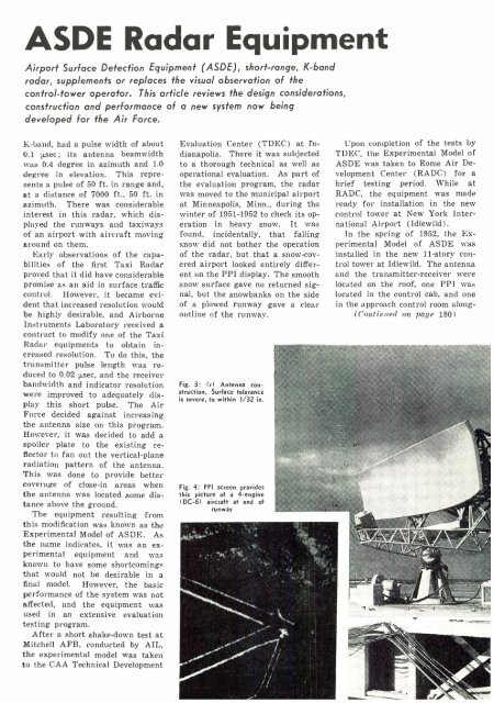
Fig. 3: (r) Antenna construction.<br />
Surface tolerance<br />
is severe, to within 1/32 in.<br />
Fig. 4: PPI screen provides<br />
this picture of a 4- engine<br />
I DC -61 aircraft at end of<br />
runway<br />
Upon completion of the tests by<br />
TDEC, the Experimental Model of<br />
ASDE was taken to Rome Air Development<br />
Center (RADC) for a<br />
brief testing period. While at<br />
RADC, the equipment was made<br />
ready for installation in the new<br />
control tower at New York International<br />
Airport (Idlewild).<br />
In the spring of 1952, the Experimental<br />
Model of ASDE was<br />
installed in the new 11 -story control<br />
tower at Idlewild. The antenna<br />
and the transmitter -receiver were<br />
located on the roof, one PPI was<br />
located in the control cab, and one<br />
in the approach control room along -<br />
(Continued on page 180)


