

TELE-TECH & - AmericanRadioHistory.Com
TELE-TECH & - AmericanRadioHistory.Com
TELE-TECH & - AmericanRadioHistory.Com

You also want an ePaper? Increase the reach of your titles
YUMPU automatically turns print PDFs into web optimized ePapers that Google loves.
j<br />
queucy. After consideration of all<br />
the factors involved -including the<br />
use of circular polarization - the<br />
conclusion was reached that other<br />
frequencies offered no real advantage.<br />
Considerable experience<br />
gained at K -band made it seem advisable<br />
to retain this frequency.<br />
In the Engineering Model, the<br />
0.02 -µsec transmitter pulse is produced<br />
by a hard -tube modulator<br />
driving a K -band magnetron. The<br />
peak power of the transmitted pulse<br />
is between 30 and 50 kw. A<br />
hydrogen thyratron pulser is used<br />
to excite the modulator and to<br />
control the pulse duration. The<br />
pulse repetition frequency of 14,400<br />
pps was chosen to give ten pulses<br />
per beamwidth. An investigation<br />
into the use of a hydrogen thyratron<br />
modulator demonstrated that<br />
thyratrons large enough to do the<br />
job would not de- ionize rapidly<br />
enough to operate at this prf. However,<br />
the smaller thyratron used in<br />
the driver circuit has proved very<br />
stable and trouble -free. One advantage<br />
of the short pulse is the fact<br />
that the operation of the magnetron<br />
is isolated from any reflections in<br />
the waveguide that occur more than<br />
8 ft. from the magnetron. Tt is interesting<br />
to realize that this magnetron,<br />
operating at 24,000 mc, generates<br />
480 cycles during a pulse.<br />
The antenna reflector is 12 ft.<br />
wide by 4 ft. high. The horizontal<br />
cross section is parabolic, while the<br />
vertical cross section is shaped to<br />
fan out the elevation beam. The<br />
vertical radiation pattern has a<br />
modified cosecant- squared distribution<br />
extending to 25° below the<br />
peak of the beam. This provides<br />
close -in coverage of the ground -<br />
for instance, giving a minimum<br />
range of 200 ft. when the antenna<br />
is mounted at a height of 100 ft.<br />
A better conception of the electrical<br />
size of the antenna can be had<br />
by considering that 12 feet represents<br />
about 300 wavelengths, or<br />
that an equivalent antenna at S-<br />
band would be almost 100 ft. wide<br />
by 30 ft. high. The tolerance on the<br />
surface of the reflector is quite severe.<br />
In order to be certain of a<br />
sidelobe level of 20 db below the<br />
peak of the beam, it is necessary to<br />
hold the surface to within -*1/64<br />
inch of the desired shape. To keep<br />
the mechanical design of the an-<br />
(Continued on page 184)<br />
<strong>Com</strong>plex Machine Tools<br />
<strong>Com</strong>puter Controlled<br />
A new numerical control device<br />
that operates complex machine<br />
tools by means of digital instructions<br />
which are automatically computed<br />
and recorded on magnetic<br />
tape has been developed by Electronic<br />
Control Systems, Inc., an<br />
affiliate of Stromberg- Carlson and<br />
a subsidiary of General Dynamics<br />
Corp.<br />
This device, called "Digimatic,"<br />
consists of 2 principle parts, a<br />
planning desk, the main part of<br />
which is a high -speed decimal<br />
computer and tape recorder, and<br />
a machine control unit which governs<br />
the operation of the machine<br />
tool from instructions on the magnetic<br />
tape.<br />
A demonstration was given in<br />
which a typical precision cam was<br />
milled from a metal blank, with<br />
the magnetic tape controlling all<br />
the operations of a vertical milling<br />
machine. To prepare for this<br />
demonstration, the dimensions of<br />
the finished part were fed into the<br />
planning desk in sequence,<br />
through a keyboard resembling<br />
that of an adding machine. The<br />
computer converts the dimensional<br />
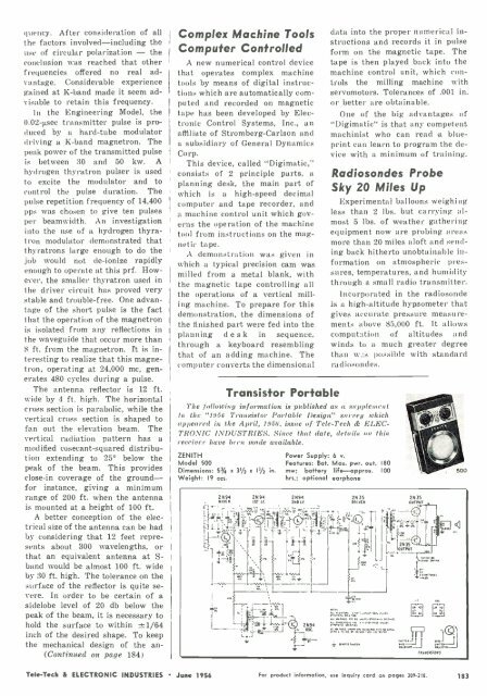
Transistor Portable<br />
The following information is published as a supplement<br />
to the "1956 Transistor Portable Design" survey which<br />
appeared in the April, 1956, issue of Tele -Tech & ELEC-<br />
TRONIC INDUSTRIES. Since that date, details ou this<br />
receiver have been made available.<br />
ZENITH<br />
Model 500<br />
Dimensions: 53/4<br />
Weight: 19 ozs.<br />
x 31/2 x 11/2 in.<br />
v Nm<br />
data into the proper numerical instructions<br />
and records it in pulse<br />
form on the magnetic tape. The<br />
tape is then played back into the<br />
machine control unit, which controls<br />
the milling machine with<br />
servomotors. Tolerances of .001 in.<br />
or better are obtainable.<br />
One of the big advantages of<br />
"Digimatic" is that any competent<br />
machinist who can read a blueprint<br />
can learn to program the device<br />
with a minimum of training.<br />
Radiosondes Probe<br />
Sky 20 Miles Up<br />
Experimental balloons weighing<br />
less than 2 lbs. but carrying almost<br />
5 lbs. of weather gathering<br />
equipment now are probing areas<br />
more than 20 miles aloft and sending<br />
back hitherto unobtainable information<br />
on atmospheric pressures,<br />
temperatures, and humidity<br />
through a small radio transmitter.<br />
Incorporated in the radiosonde<br />
is a high -altitude hypsometer that<br />
gives accurate pressure measurements<br />
above 85,000 ft. It allows<br />
computation of altitudes and<br />
winds to a much greater degree<br />
than w is possible with standard<br />
radiosondes.<br />
Power Supply: 6 v.<br />
Features: Bat. Max. pwr. out. 180<br />
mw; battery life -approx. 100<br />
hrs.; optional earphone<br />
1 2N94<br />
osc.<br />
bq-.<br />
1 ,,.,.0<br />
2N35<br />
DRIVER<br />
_J<br />
2UTN3<br />
OPU5T<br />
2X35<br />
OUTPUT<br />
1:;=__11<br />
I1<br />
r>,.<br />
rNNNSISIORS<br />
uJ<br />
Tele -Tech &<br />
ELECTRONIC INDUSTRIES<br />
June 1956 For product information, use inquiry card on pages 209 -210. 183


