

TELE-TECH & - AmericanRadioHistory.Com
TELE-TECH & - AmericanRadioHistory.Com
TELE-TECH & - AmericanRadioHistory.Com

You also want an ePaper? Increase the reach of your titles
YUMPU automatically turns print PDFs into web optimized ePapers that Google loves.
1.8<br />
Finned Magnetron<br />
The increased power demands on magnetrons,<br />
and their use in airborne equipment<br />
has created a need for a light weight,<br />
economical cooling system. Forced air<br />
cooling, using properly designed cooling<br />
fins, is described here as a logical solution<br />
PUNCHING DETAIL<br />
SECTION A -A<br />
RIB DETAIL<br />
SECTION 8 -8<br />
attached by heat conducting paths.<br />
These must be highly conductive or<br />
the large temperature drop from<br />
the component to the exchanger<br />
surface will destroy the gains obtained<br />
by the large hS value of the<br />
heat exchanger, h being the average<br />
heat transfer coefficient and S<br />
the heat transfer surface area.<br />
Fins, which increase the heat transfer<br />
surface area by the addition of<br />
a secondary surface area, are an<br />
example of a simple type of heat<br />
exchanger.<br />
The surface temperature (ta) of<br />
the electronic part is fixed by the<br />
allowable component temperature,<br />
generally a hot spot tmperature;<br />
the fluid or coolant temperature<br />
(te) is given by whatever may be<br />
available for the cooling system,<br />
and the heat dissipated (q) depends<br />
upon the component dissipation.<br />
Consequently, knowing values for<br />
these quantities, one may define an<br />
overall hS product required of the<br />
particular cooling system.<br />
q<br />
(11í') = - (I)<br />
required (t - te)<br />
The hS value available is a function<br />
of the coolant mass rate of flow<br />
W and the cooling system. For any<br />
particular system a plot can be<br />
made of (hS)neeil;,,,, vs. W (see<br />
Fig. 1). In addition, a plot of Ap<br />
vs. W can be made (see Fig. 1).<br />
The curve in Fig. 1 applies only for<br />
the particular coolant density involved;<br />
however this can be easily<br />
corrected for other values of density,<br />
assuming incompressible flow.<br />
Entering the (hS) n, eiiai,re curve with<br />
the value obtained from Eq. 1, the<br />
Dr. M. MARK, Consulting Engr., 1384 Mass.<br />
Ave., Cambridge 38, Mass. (The work described<br />
in this article was performed while<br />
the author was employed at Raytheon Mfg.<br />
Co., Newton, Mass.)<br />
A --<br />
0 A U<br />
a B<br />
a<br />
Description<br />
Table I<br />
Flow, cubic<br />
ft.,min.<br />
:1p, in.<br />
of water<br />
Ideal Air<br />
horsepower<br />
Original fin (Fig. 3) 37.5 8.0 .0473<br />
Deflector insert (Fig. 5) 29 2.8 .0128<br />
Streamlined exit (Fig. 5) 27.5 2.1 .0091<br />
Punchings and ribs (Fig. 6) .... 18 2.2 .0062<br />
Punchings, ribs and streamlined<br />
exit ( Fig. 7) 18 1.9 .0054<br />
Addition of finned output, and fins<br />
of Fig. 7 (see Fig. 8) 15<br />
I .0043<br />
Data for hS = 6.25 w. / °C -(t, ,<br />
PUNCHING DETAIL<br />
RIB DETAIL<br />
SECTION A -A SECTION 68<br />
W required can be obtained. With<br />
this value of W, the necessary .1p<br />
can be determined, and finally the<br />
horsepower required for cooling.<br />
For a magnetron with a given<br />
cooling system, hS can be defined in<br />
terms of the hot spot temperature<br />
t, 111,,, the inlet coolant temperature<br />
tr,1n1 ,, and the heat dissipated q,<br />
from Eq. 1.<br />
q = hS (t,.,, - tr.leel,.,) (2)<br />
To obtain the curve for (hS)n,e,la,,ie<br />
for a particular cooling system, the<br />
quantities q and (ta .1aax tr.151et) are<br />
measured at various values of flow<br />
i<br />
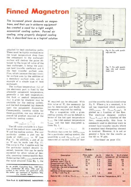
Fig. 6: Fin with punch<br />
inns and ribs<br />
Fig. 7: Fin with punch -<br />
ings, ribs and streamlined<br />
exit<br />
and the quantity hS calculated using<br />
Eq. 2. Where q is a constant, it is<br />
not too important which quantity,<br />
(hS)nrnilahl or (ts.max tf.iniet), is<br />
plotted as a function of the flow.<br />
The electrical designer prefers<br />
(ts.maz tr.inl t) as a function of the<br />
flow; consequently, this form is<br />
commonly used in electrical work to<br />
present heat transfer results where<br />
a constant heat dissipating element<br />
is involved. However, it is not as<br />
general a form for the results as<br />
the hS vs. W plot.<br />
(Continued on page 174)<br />
° , - tr.)°LL) = 40 °C -Inlet Air Temperature, 30 °C<br />
% of originel<br />
air horsepowar<br />
100<br />
27<br />
19<br />
13<br />
11<br />
9<br />
Tele -Tech & ELECTRONIC INDUSTRIES<br />
J une 1956<br />
101


