annual report annual report annual report annual report 2005
annual report annual report annual report annual report 2005
annual report annual report annual report annual report 2005

Create successful ePaper yourself
Turn your PDF publications into a flip-book with our unique Google optimized e-Paper software.
NUCLEAR TECHNOLOGIES AND METHODS 141<br />
is practically the same as the jitter of a nanosecond<br />
modulator (5 kV/10 ns) of the electron gun grid [6].<br />
A detailed consideration of the problem revealed<br />
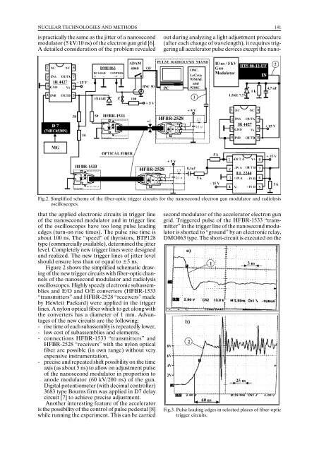
Fig.2. Simplified scheme of the fiber-optic trigger circuits for the nanosecond electron gun modulator and radiolysis<br />
oscilloscopes.<br />
that the applied electronic circuits in trigger line<br />
of the nanosecond modulator and in trigger line<br />
of the oscilloscopes have too long pulse leading<br />
edges (turn-on rise times). The pulse rise time is<br />
about 100 ns. The “speed” of thyristors, BTP128<br />
type (commercially available), determined the jitter<br />
level. Completely new trigger lines were designed<br />
and realized. The new trigger lines of jitter level<br />
should ensure less than or equal to ±5 ns.<br />
Figure 2 shows the simplified schematic drawing<br />
of the new trigger circuits with fiber-optic channels<br />
of the nanosecond modulator and radiolysis<br />
oscilloscopes. Highly speedy electronic subassemblies<br />
and E/O and O/E converters (HFBR-1533<br />
“transmitters” and HFBR-2528 “receivers” made<br />
by Hewlett Packard) were applied in the trigger<br />
lines. A nylon optical fiber which to get along with<br />
the converters has a diameter of 1 mm. Advantages<br />
of the new circuits are the following:<br />
- rise time of each subassembly is repeatedly lower,<br />
- low cost of subassemblies and elements,<br />
- connections HFBR-1533 “transmitters” and<br />
HFBR-2528 “receivers” with the nylon optical<br />
fiber are possible (in own range) without very<br />
expensive instrumentation,<br />
- precise and repeated shift possibility on the time<br />
axis (as about 5 ns) to allow on adjustment pulse<br />
of the nanosecond modulator in proportion to<br />
anode modulator (60 kV/200 ns) of the gun.<br />
Digital potentiometer (with decimal controller)<br />
3683 type Bourns firm was applied in D7 delay<br />
circuit [7] to achieve precise adjustment.<br />
Another interesting feature of the accelerator<br />
is the possibility of the control of pulse pedestal [8]<br />
while running the experiment. This can be carried<br />
out during analyzing a light adjustment procedure<br />
(after each change of wavelength), it requires triggering<br />
all accelerator pulse devices except the nanosecond<br />
modulator of the accelerator electron gun<br />
grid. Triggered pulse of the HFBR-1533 “transmitter”<br />
in the trigger line of the nanosecond modulator<br />
is shorted to “ground” by an electronic relay,<br />
DMO063 type. The short-circuit is executed on the<br />
Fig.3. Pulse leading edges in selected places of fiber-optic<br />
trigger circuits.